Description
In this electronics project, I have explained how to make an automatic water pump switch using the 555 timer IC. The pump will automatically ON and OFF according to the water level in the tank.
Related Article: Water Pump controller with Underground and Overhead Tank Automation
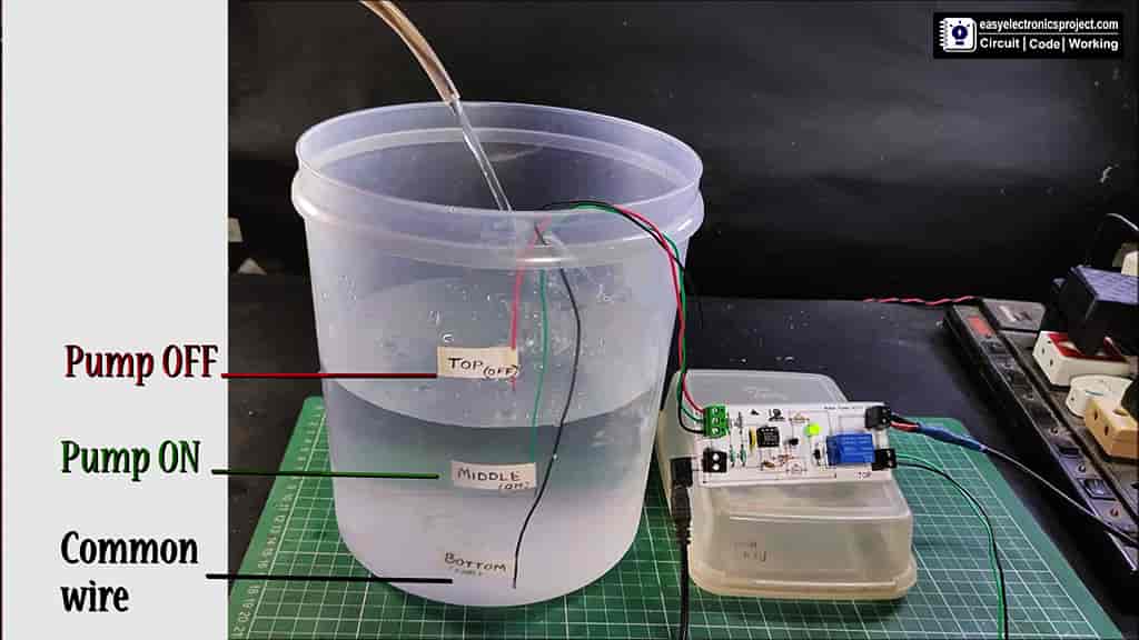
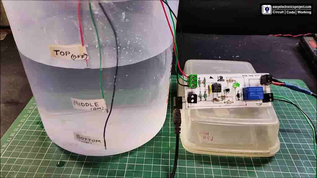
The pump will automatically turn on if the water level in the tank decrease (cross the green wire). And the Pump will stop when the water level touch the red wire.
Circuit of Automatic Water Pump Switch
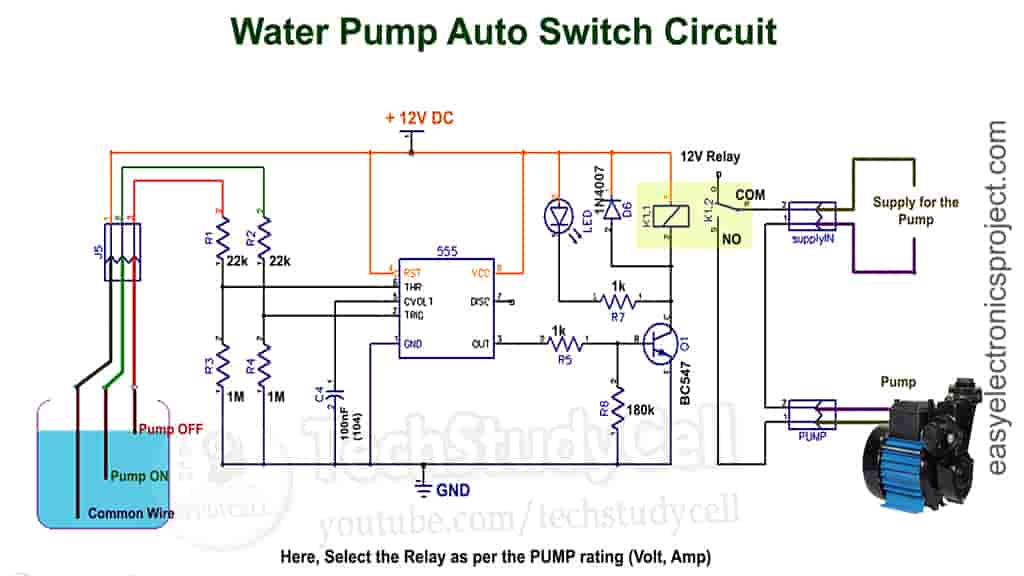
The circuit is very simple, You can easily make this project with some basic electronics components.
You have to select the Relay as per the Pump voltage and current rating.
Relay coil voltage: 12V DC
Relay Contact Rating: As per the Pump rating
PCB Layout for Auto Pump Switch
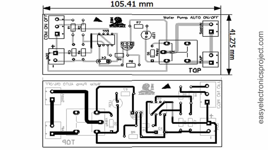
Please download the PCB layout, then print it on the A4 page.
Please check the PCB size while printing, it should be the same as mentioned
Required Components:
- 555 Timer IC (1no)
- BC547 NPN Transistor (1no)
- 1k 0.25-watt Resistors (R5, R7) (2no)
- 22k 0.25-watt Resistors (R1, R2) (2no)
- 180k 0.25-watt Resistor (R6) (1no)
- 1M 0.25-watt Resistors (R3, R4) (2no)
- LED 1.5V 5-mm (1no)
- 1N4007 Diode (D6) (1no)
- 100nF (104) Capacitor (C4) (1no)
- 12V SPDT Relay (1no)
- Connectors & IC base (4 pin)
- Zero PCB or card board
Tutorial Video on Water Pump Auto-Cut Switch
In this tutorial video, I have shown all the steps to make the Auto Cut Water Pump ON-OFF Switch circuit. So please watch the video for better understanding.
How to make Automatic Water Pump PCB
Steps for making the Automatic Battery Charger circuit on PCB:
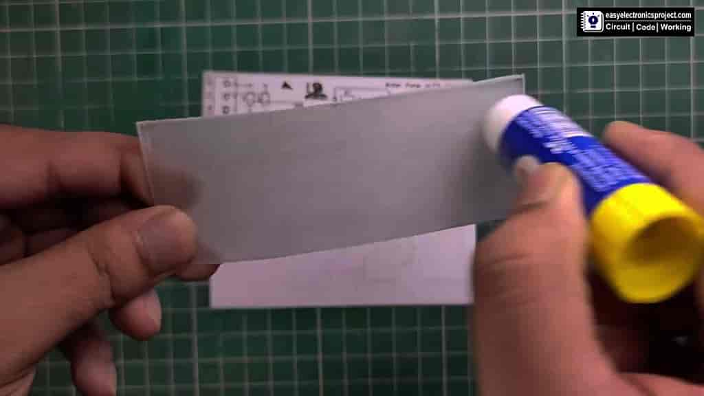
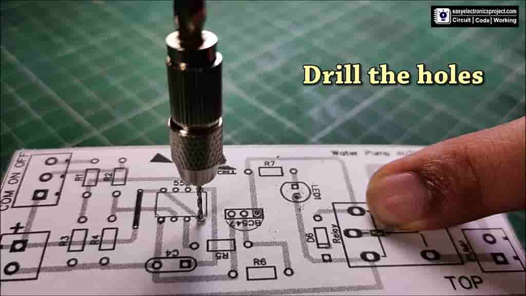
- Print the PCB Layout and stick it on cardboard or Acrylic sheet.
While printing please consider the PCB size mentioned in the PCB layout.
- Drill the holes for the components as shown on PCB Layout
- Connect all the components as shown on the PCB layout
Now, place all the components on the PCB as shown, then solder all the components as per the circuit.
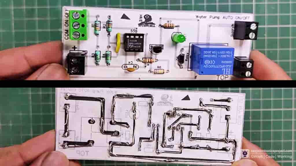
Now, the PCB for Water Pump Auto ON-OFF circuit is ready.
Connect the Water Pump
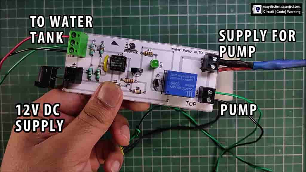
Now, connect the water pump and supply as shown in the above picture.
Please take proper safety precaution while working with 220V /110V supply.
Finally, Automatic Water Pump Switch is ready
Please share your feedback on this mini-project and also let me know if you have any queries.
You can also subscribe to our newsletter to receive more such useful electronics projects through email.
I hope you have liked this projects, Thank you for your time.