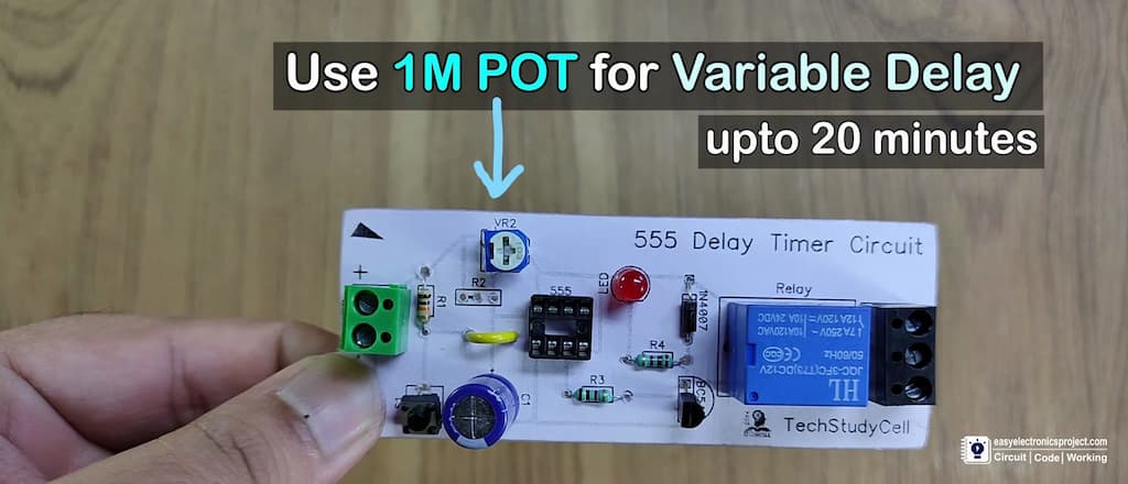
In this 555 timer project, I have shown how to make a time delay relay circuit using 555 timer IC to automatically turn Off the switch after a predefined delay.
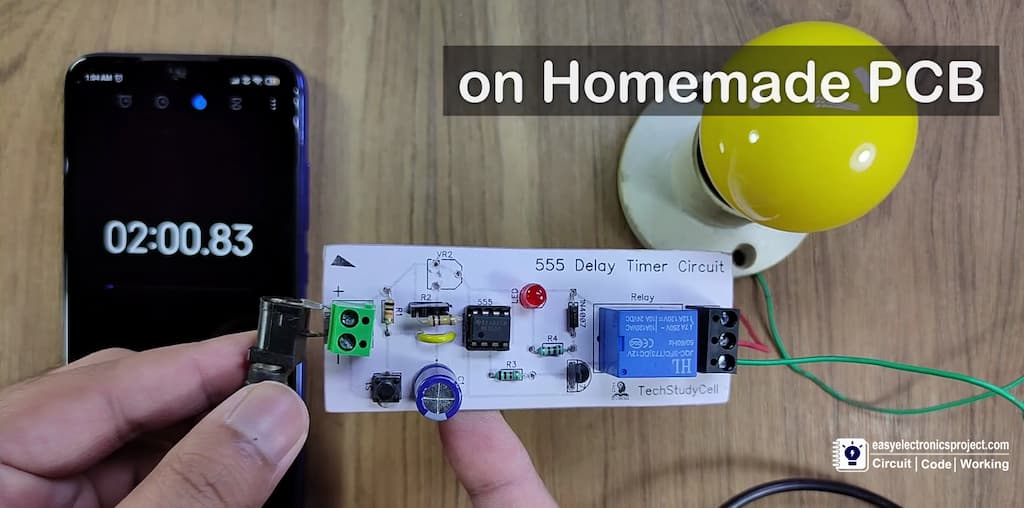
You can also adjust the off delay time up to 20 minutes with a 1M POT.
In this article, I have shared the required components, complete circuit diagram, PCB layout, and all other details for this simple 555 timer project.
Time Delay Relay Circuit Diagram
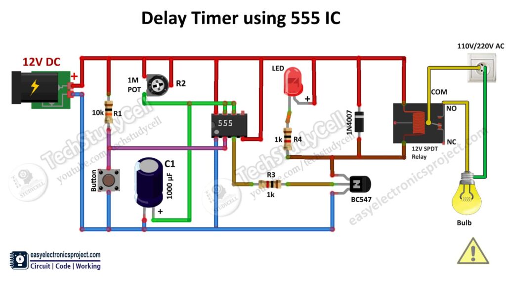
In this circuit, if you want to use the 5V DC supply, then use the 5-volt relay instead of the 12-volt relay.
The delay time depends on the R2 resistor and C1 capacitor. For the constant delay time use a fixed resistor in R2, but for the adjustable off delay time, you can use a 1M POT.
I will discuss how this circuit works later in this article.
PCB Layout for Delay Timer circuit
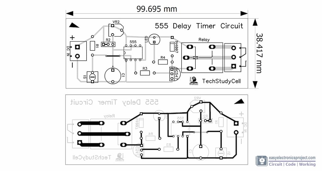
Please download the PCB layout, then print it on the A4 page.
Please check the PCB size while printing, it should be the same as mentioned.
You can also download the PCB Gerber file for this project.
Required Components for Time Delay Relay
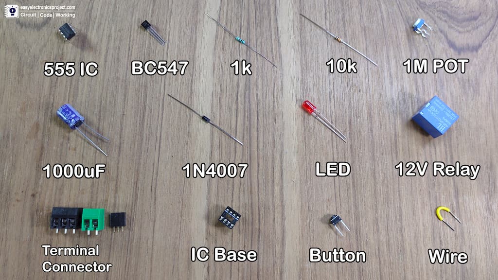
- 555 Timer IC
- BC547 NPN Transistor
- 1000uF 16V Capacitor (C1)
- 1k 0.25watt Resistors – 2 no (R3, R4)
- 10k 0.25watt Resistor (R1)
- 1M Trimmer POT (R2)
- LED 5mm – 1no
- 1N4007 Diode
- 12V SPDT Relay
- Pushbutton
- Connectors & IC Base
Tutorial Video on this 555 timer Project
In this tutorial video, I have explained all the steps to make the homemade PCB for the LED chaser light circuit. To make the PCB I have used an acrylic sheet.
How to make DIY PCB using plastic sheet
You can also order the custom design PCB for this electronics project from PCBWay.
About PCBWay and their services
- PCB Prototyping and Manufacturing
PCBWay not only produce FR-4 and Aluminum boards, but also advanced PCB like Rogers, HDI, Flexible and Rigid-Flex boards, with very reasonable price.
For the online instant quote page please visit – pcbway.com/orderonline
Inspect your Gerber file before placing the order – OnlineGerberViewer - PCB assembly
The SMT & THT assembly starts from only $30 with the free stencil and free worldwide shipping.
The components can be sourced and provided by us, or by clients themselves
Rough quote online – pcbway.com/pcb-assembly
With PCBWay you can also get the following benefits
- No Minimum Requirement
- Fair Pricing
- Free DFM
- On-time Shipping
- Return and Refund
- 24 hours Customer Service
For more details please visit Why PCBway.
You can also explore different PCB projects from their Open-source community pcbway.com/project/.
Steps to order PCB from PCBWay
To order the PCB first visit PCBWay.com.

Then enter the following details:
- PCB Size (Length & Width) in mm & PCB quantity
- Select masking color for the PCB
- Select country and shipping method
- Click on the “Save to Cart” button
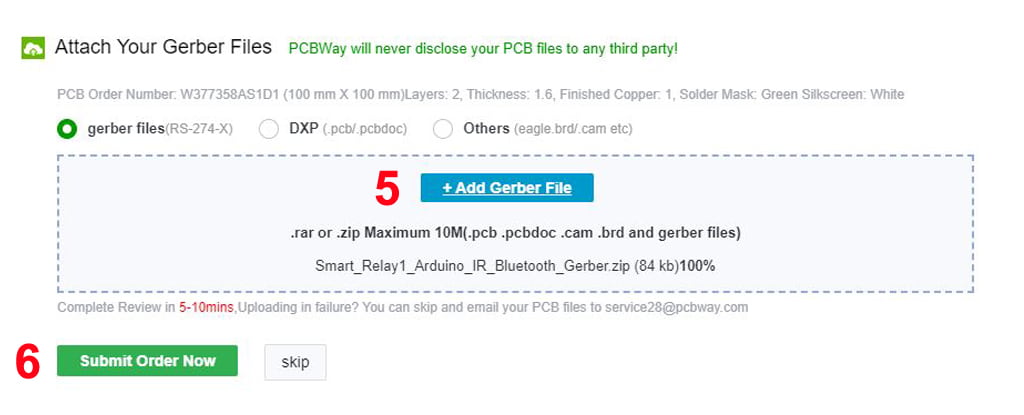
Now click on the “Add Gerber Files” to upload the PCB Gerber file.
Then click on the “Submit Order Now” to place the order.
After that, they will review the Gerber file and accordingly confirm the order.
I have used their services for my different electronics projects, I always received the PCB on time and the quality is very good in this price range.
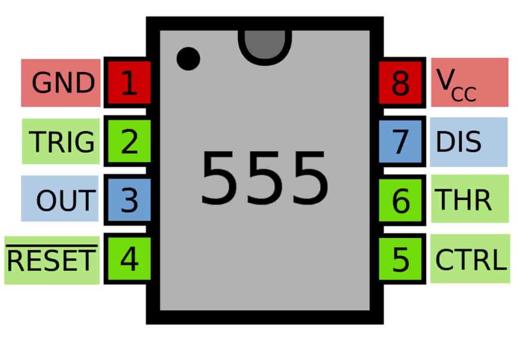
How does the Circuit Works?
- If the Trigger Pin (Pin-2 of the 555 IC) senses any voltage less than 1/3rds of the supply voltage, it turns ON the output.
- If the Threshold Pin (Pin-6 of the 555 IC) senses any voltage more than 2/3rds of the supply voltage, it turns OFF the output.
- Whenever the output of the 555 IC is in OFF state, the Discharge Pin (Pin-7 of the 555 IC) acts as ground i.e, it is internally connected to 0V.
Keeping the above 3 points in mind, let’s try to understand how this circuit works.
Initially, when this circuit is powered on, the output will be in the OFF state. Whenever the output is OFF, the discharge pin (Pin 7) will be internally connected to 0V. So the capacitor completely discharges and won’t be able to charge via the series resistor that connects it to the positive input voltage.
When the momentary push-button is pressed, the off delay timer is activated, and the following sequence occurs:
- 0V is applied at the trigger pin (Pin-2) via the push-button.
- Since this applied voltage (0V) at Pin-2 is less than 1/3rd of the input voltage, the output (Pin-3) turns ON
- Parallel to this, the discharge pin (Pin-7) disconnects internally with 0V.
- So now the capacitor starts charging via the resistor/potentiometer (R2) that connects it to the positive input voltage (VCC).
- Since the threshold pin (Pin-6) is connected to the positive terminal of the capacitor (C1), it actively monitors the voltage across it.
- As soon as the capacitor charges to 2/3rd of the input voltage, the threshold pin (Pin-6) turns OFF the output (Pin-3). (This time period for which the capacitor charges from 0V to 2/3rd of input voltage is the delay time)
- As soon as the output turns OFF, discharge Pin (Pin-7) is internally re-connected to 0V and the capacitor (C1) is discharged completely.
The above steps are repeated each time the momentary push-button is pressed.
Calculation for the Delay Time
According to our delay timer circuit, the time duration is equal to the time taken for the capacitor to charge from 0V to 2/3rd of the input voltage, and theoretically, the value is equal to:
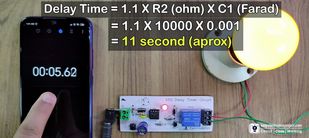
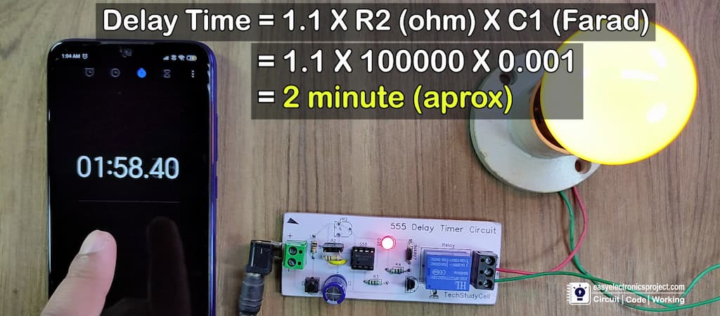
T (in seconds) = 1.1 * R (in ohm) * C (in Farad)
[in the circuit, R is R2 and C is C1]
Practically, the delay time will be higher than the calculated value due to the leakage of the capacitor (C1).
Example 1: with 10k resistor as R2 [10k = 10000 ohm]
Example 2: with 100k resistor as R2 [10k = 100000 ohm]
If you use 1M POT, then you can get an off time delay of up to 20 minutes.
Please share your feedback on this mini-project and also let me know if you have any queries.
You can also subscribe to our newsletter to receive more such useful electronics projects through email.
I hope you have liked this electronics project, Thank you for your time.
