Description:
This is an automatic street light circuit using LDR and BC547 on the breadboard. With this simple automatic street light control system, we can control a 230v street light using a relay. The 220 volt AC bulb will automatically turn on after the sunset and turn off after sunrise. This photoresistor circuit also can be used as an emergency light.
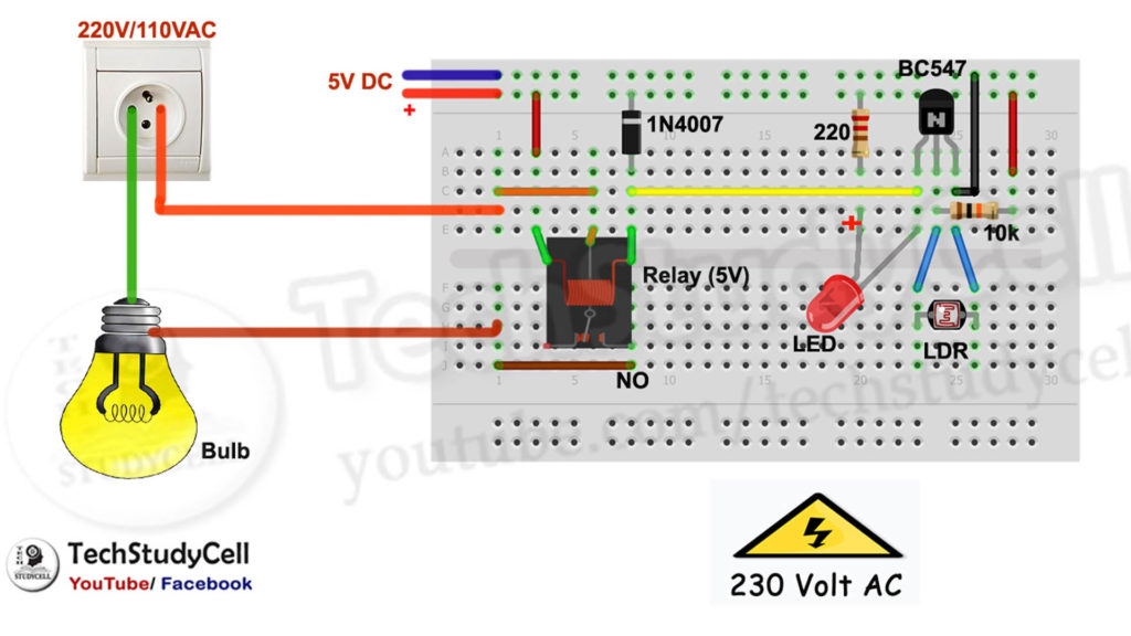
Circuit Diagram of Automatic Street Light:
Component List:
1. BC547 Transistor,
2. LDR
3. 220-ohm Resistor
4. 10k Resistor
5. LED 5mm
6. 1N4007 Diode
7. SPDT Relay 5V
8. AC Bulb 220V
9. 5V DC source or Mobile Charger
10. Breadboard
Working Principle:
How LDR street light works:
The resistance across the LDR varies with the light intensity falls on it. When the light intensity is high, the resistance across the LDR is low so the Base of the transistor BC547 is connected to ground through LDR.
Current Path: +5v –> 10k Resistor –> LDR –> GND.
As no positive pulse at Base of the BC547 so the transistor turns off. So current can flow through the relay coil and the AC lamp connected with the Relay turns on.
If the light intensity becomes low then the resistance becomes very high across LDR. So the current through the 10k resistor cannot flow through the LDR. Then the current through 10k resistor fed positive pulse to Transistor Base. Then the NPN transistor turns on.
Current Path: +5v –> 10k Resistor –> Base BC547
So current can flow through the relay coil and the AC lamp connected with the Relay turns on.
Thus we can use a LDR to make this automatic street light.
Tutorial Video:
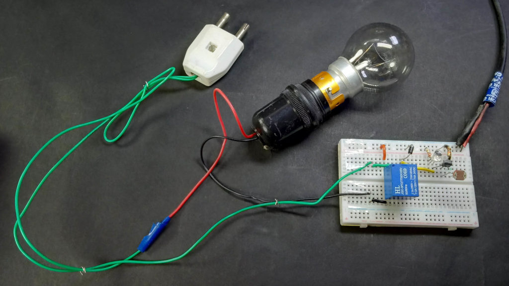
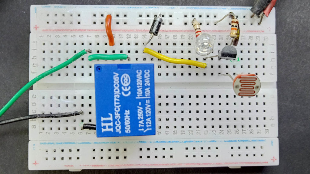
Photos of the LDR Project:
