Description:
This is a simple 12v LED dimmable circuit using a 555 timer ic. We can easily control LED brightness using a potentiometer with this 555 PWM LED dimmer circuit.
The 555 timer ic will generate the PWM signal and we can adjust the duty cycle with a potentiometer. As we will use PWM to control the brightness of the LED lights so this Dimmable LED light is also very efficient and can be made easily with some basic electronics components.
Circuit Diagram of Dimmable LED:
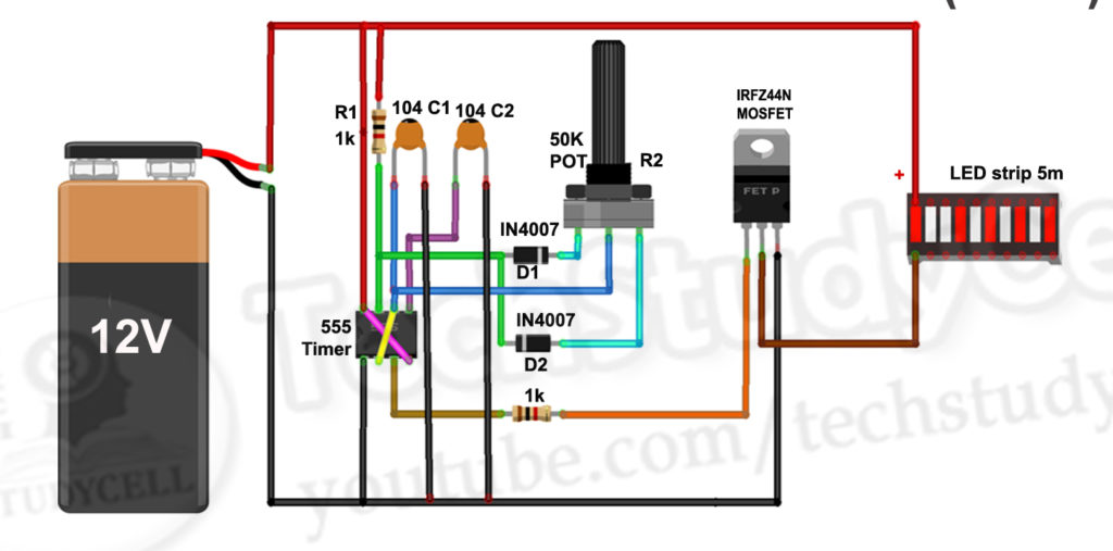
Component List of Dimmable LED:
1. 555 timer ic 1no
2. IRFZ44N MOSFET 1no
3. 50k Potentiometer or trimmer 1no
4. 0.1uF ceramic capacitor 2no
5. 1k Resistors 2no
6. 1N4007 Diodes 2no
7. Breadboard
8. 12volt DC power supply
9. LED strip 12v
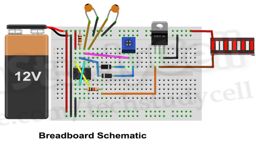
Breadboard Schematic:
Working Principle of LED Dimmer:
The 555 timer Astable arrangement creates a square wave with time high and time low. The ratio of these times can be varied by changing R1, R2, and C1 in the typical 555 astable arrangement.
Here, we have made R2 (50K POT) as a variable resistor for changing the duty cycle of the output signal. Capacitor C1 Charging through D1 diode and Discharge through D2 diode, which will generate a PWM signal at 555 timer’s output pin (PIN3) and accordingly the MOSFET turns on and off.
The time the square wave is high can be calculated by 0.7 x (R1+R2) x C1
The time the square was is low can be calculated by 0.7 x R2 x C1
Related Video:
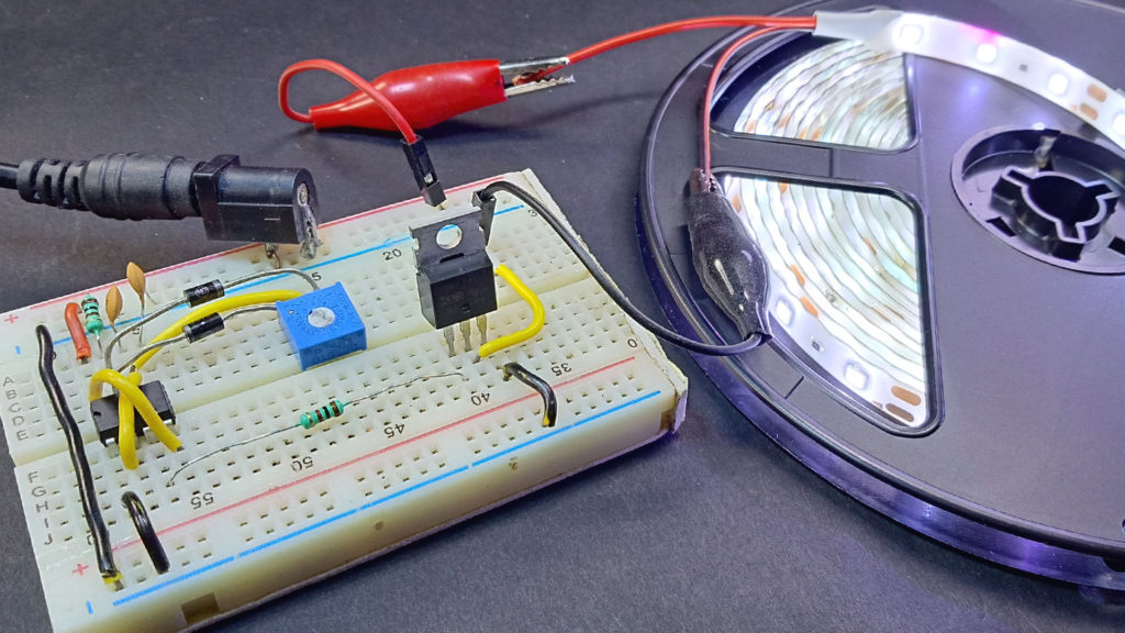
Photos of the Dimmable LED Project:

