An automatic water pump controller for a submersible pump is a convenient and efficient solution for maintaining the water level in a tank or reservoir. This 555 IC circuit ensures that the pump operates only when the water level falls below a certain point, preventing dry running and water overflow. In this article, we will discuss the basic design and operation of an automatic water level controller circuit for a submersible pump.
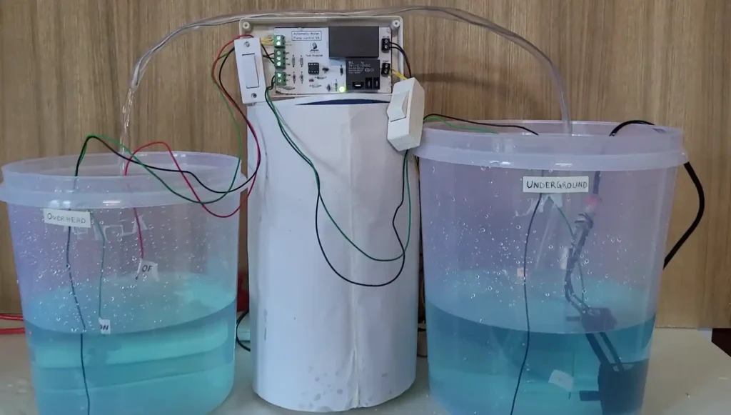
When the water level in the overhead tank drops below the green wire, the pump will start automatically. Conversely, when the water level in the overhead tank reaches the red wire, the pump will shut off automatically.
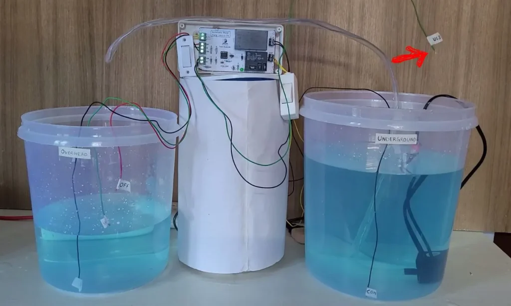
If the water level in the underground tank falls below the UL1 level, the pump will automatically stop, even if the water level in the overhead tank is low.
There are also AUTO and MANUAL modes. To go to AUTO mode, turn OFF the manual switch and then turn ON the AUTO switch. And to go back to MANUAL mode, turn OFF the AUTO switch.
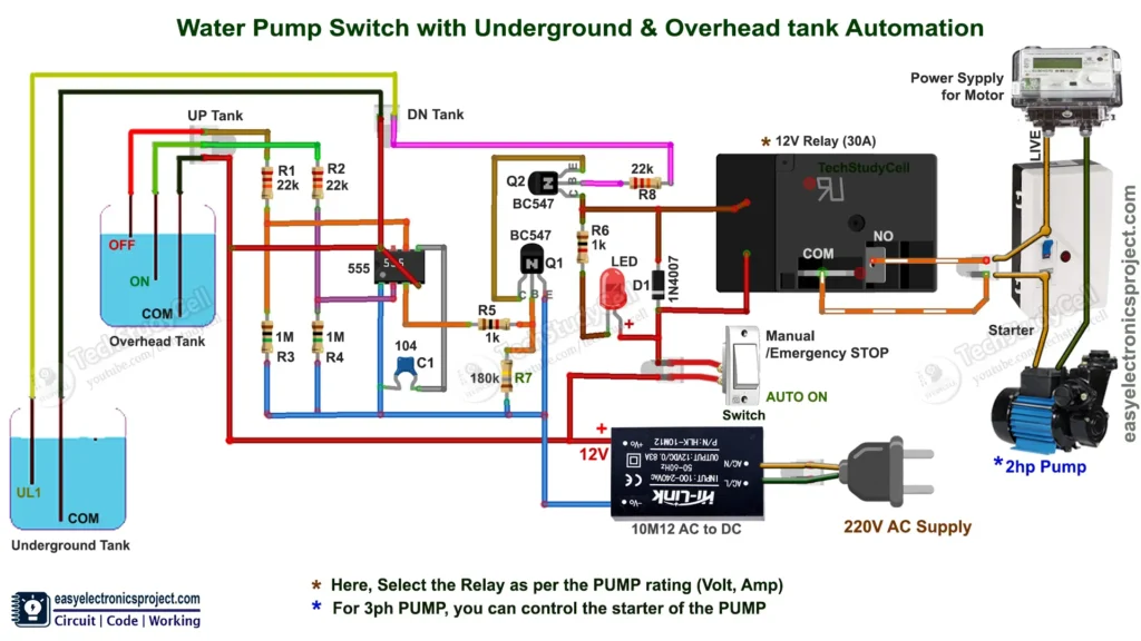
Circuit of Automatic Water Pump Controller
The circuit is simple, requiring only basic electronic components, making it easy to create this project.
To create this water pump controller, I utilized a 555 IC. Additionally, I used a 30A relay that can support pumps up to 2 HP.
When selecting a relay, ensure it matches the voltage and current rating of your specific pump.
Relay coil voltage: 12V DC
Relay Contact Rating: As per the Pump rating
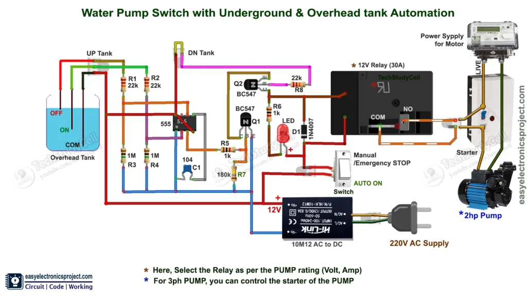
If you don’t need dry run protection or you don’t have an underground tank then short the UL1 and COM terminals as per the following circuit.
PCB Layout for Automatic Water Pump Controller
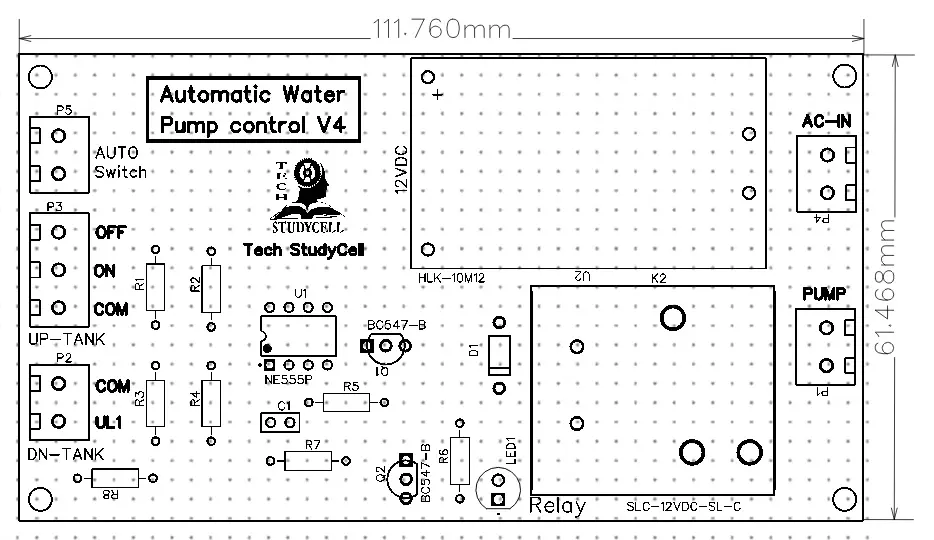
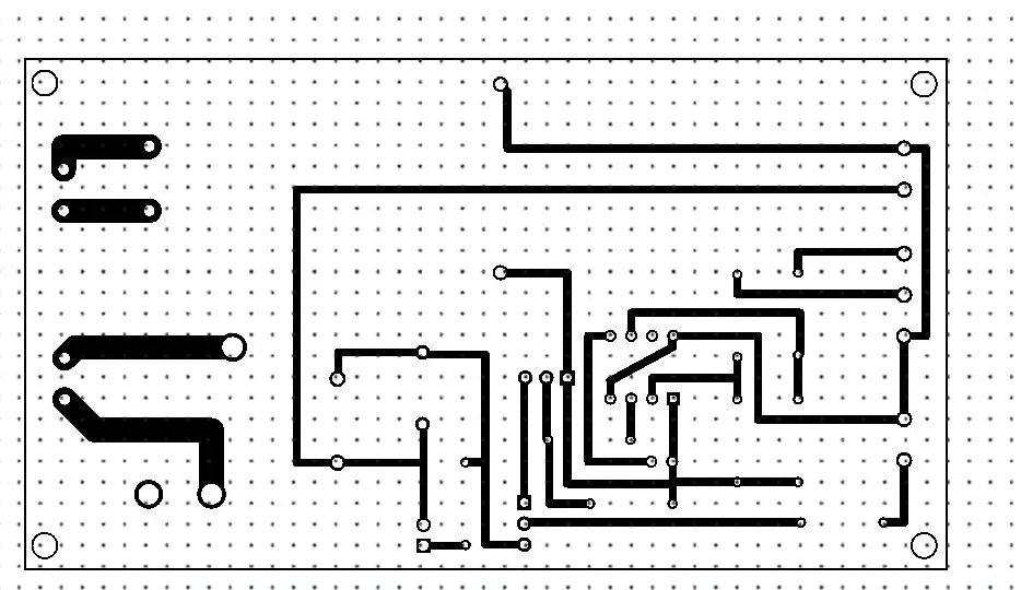
Please download the PCB layout, then print it on the A4 page.
Please check the PCB size while printing, it should be the same as mentioned.
** Refer to the docx file for printing.
Required Components:
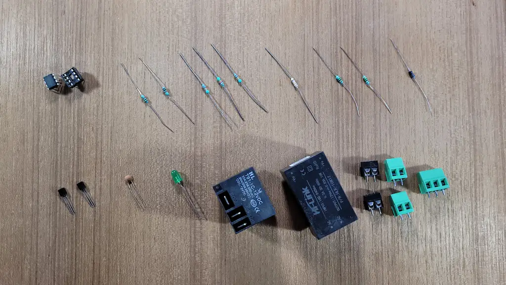
- 555 Timer IC (1no)
- BC547 NPN Transistor (2no) (Q1, Q2)
- 1k 0.25-watt Resistors (2no) (R5, R6)
- 22k 0.25-watt Resistors (3no) (R1, R2, R8)
- 180k 0.25-watt Resistor (1no) (R7)
- 1M 0.25-watt Resistors (2no) (R3, R4)
- LED 1.5V 5-mm (1no)
- 1N4007 Diode (D1) (1no)
- 100nF (104) Capacitor (C1) (1no)
- 12V SPDT Relay (Contact Rating 30A) (1no)
- Connectors & IC base (4 pins)
- Switch (1no)
- Zero PCB
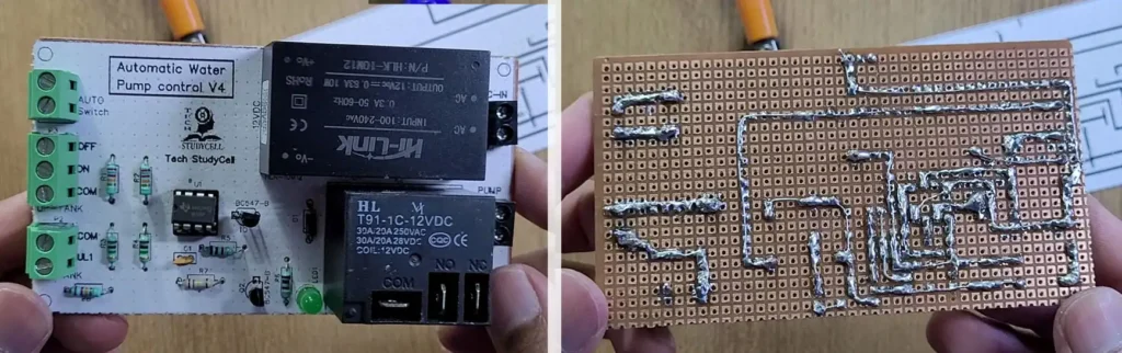
Tutorial Video on Automatic Pump Controller
In this tutorial video, I have explained all the steps to make the homemade PCB for the automatic pump switch circuit. I have made the complete circuit on the zero PCB.
But you can also download the PCB Gerber file for this project, and order the custom design PCB from PCBWay.com
About PCBWay and their services

You can order any custom design PCB from PCBWay at a very affordable price.
To mark PCBWay’s 9th anniversary, they’re offering exciting discounts as a token of appreciation for their customers’ support. With exclusive offers and special incentives, customers now have a great opportunity to benefit from these limited-time deals.

Enjoy free coupons, modules, special deals, and sponsorship, and experience their leadership in PCB fabrication and assembly.
For more details please click here.
Connection diagram of the Pump Control PCB
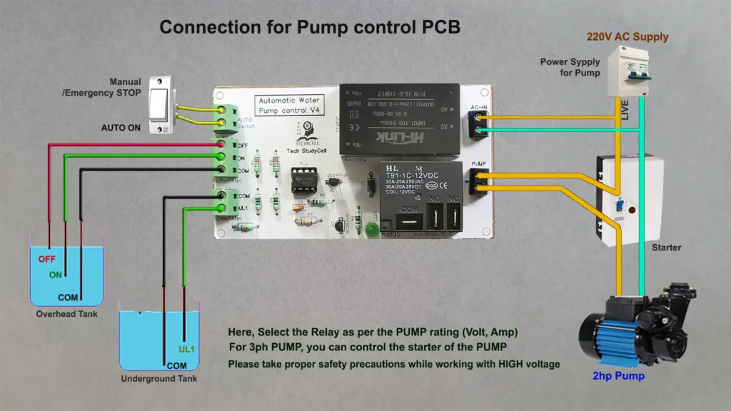
Please note down the following point before making the circuit.
- Here, I have used 30A Relay, so you can easily control most of the 1-ph pump.
- For the 3ph pump, you can control the starter coil with this circuit.
- Do not coil the water level sensing wires together, keep them separate.
- The pump will automatically start for the following conditions
- The overhead tank water level comes below the “ON” level.
- The underground water level is above UL1 level.
- The circuit is in Auto Mode (Auto Switch is ON).
- The pump will automatically stop for the following conditions
- The overhead tank water level touches the “OFF” level.
- The underground water level comes below the UL1 level.
- The circuit is in Auto Mode (Auto Switch is ON).
- NO and COM terminals of the relay are connected across the existing manual switch of the pump.
- If you don’t have an underground tank connect the UL1 and COM terminals (as shown in the second circuit).
- Please take proper safety precautions while working with high voltage.
Before connecting the pump, you can also test the circuit with a 220V AC lamp.
Please share your feedback on this mini-project and also let me know if you have any queries.
I hope you have liked this electronics project, Thank you for your time.