In this 4017 project, I have shown how to make an IR sensor switch using the 4017 IC and 1738 IR receiver IC to control an AC lamp from any IR remote without using any microcontroller or Arduino. You also control the lamp manually from the push button.
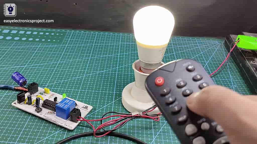
To control the lamp you just have to press any button on IR remote, and to turn it off you have to press the button again. You can use any IR remote.
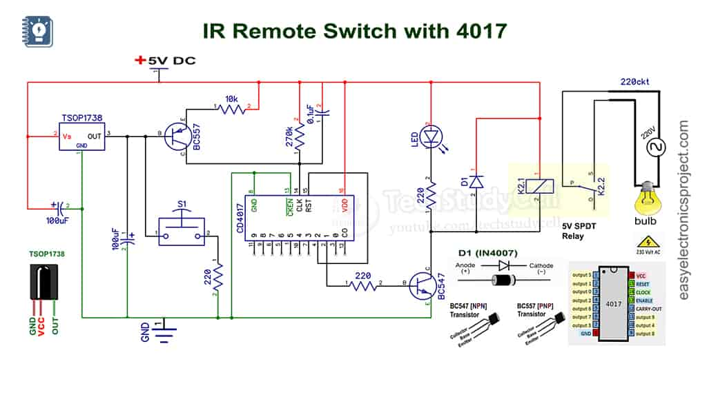
Circuit of IR Sensor Switch
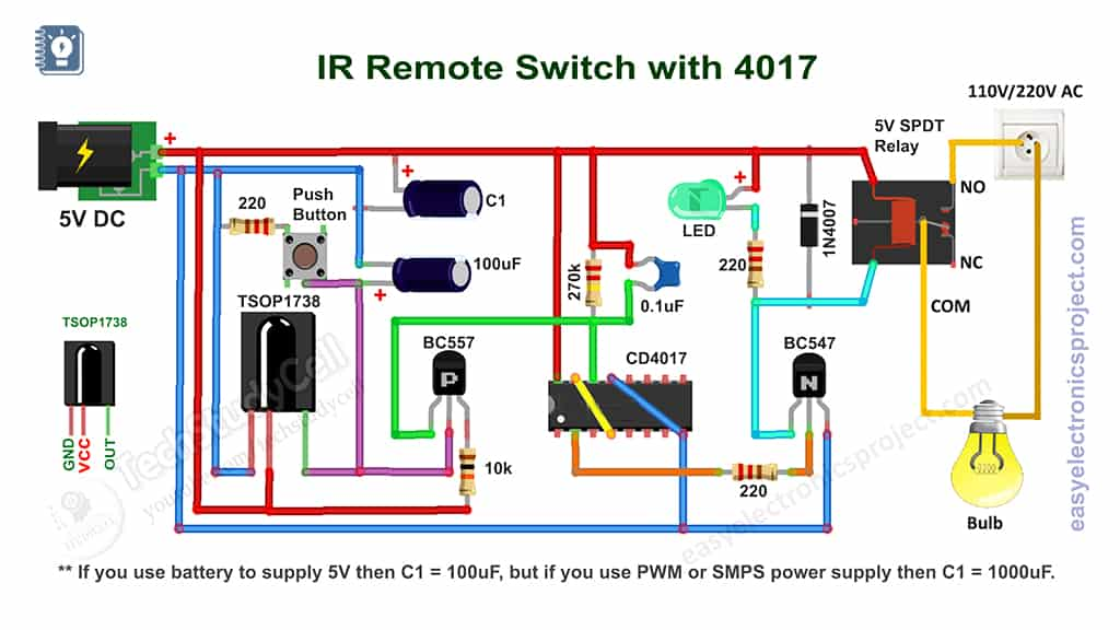
The IR remote switch circuit is very simple. I have used the CD4017 and TSOP1738 IR receiver IC to make this IR sensor switch. Use a 1000uF capacitor as C1 to avoid any issue.
How the IR Sensor Switch works
- When anyone presses the IR remote button, it emits an infrared signal, the 1738 IR receiver detects the IR signal, and the output pin of 1738 becomes LOW.
- The Base of the BC557 PNP transistor connected with the output pin of the 1738 IC. So when 1738 output becomes LOW the BC557 PNP transistor turns on.
- The BC557 connected with the CLK pin (pin 14) of CD4017 IC. When the BC557 turns on, the CD4017 CLK pin receives a HIGH pulse.
- Each time the CLK pin of CD4017 received a HIGH pulse, the state of the PIN-2 of CD4017 changes. For example, if the current state of PIN-2 is LOW, after receiving a clock pulse the PIN-2 will become HIGH till the next clock pulse.
- If the PIN-2 becomes HIGH, the BC547 NPN transistor turns ON, and the current can flow through the relay coil. so the load connected with the relay also turns on.
- If the IR remote button pressed second time, the CD4017 will receive the next clock pulse at PIN-14. So the PIN-2 will change the state (HIGH to LOW). Then the BC547 transistor will turn off and accordingly the load connected with the really also turn off.
PCB Layout of the IR Sensor Switch
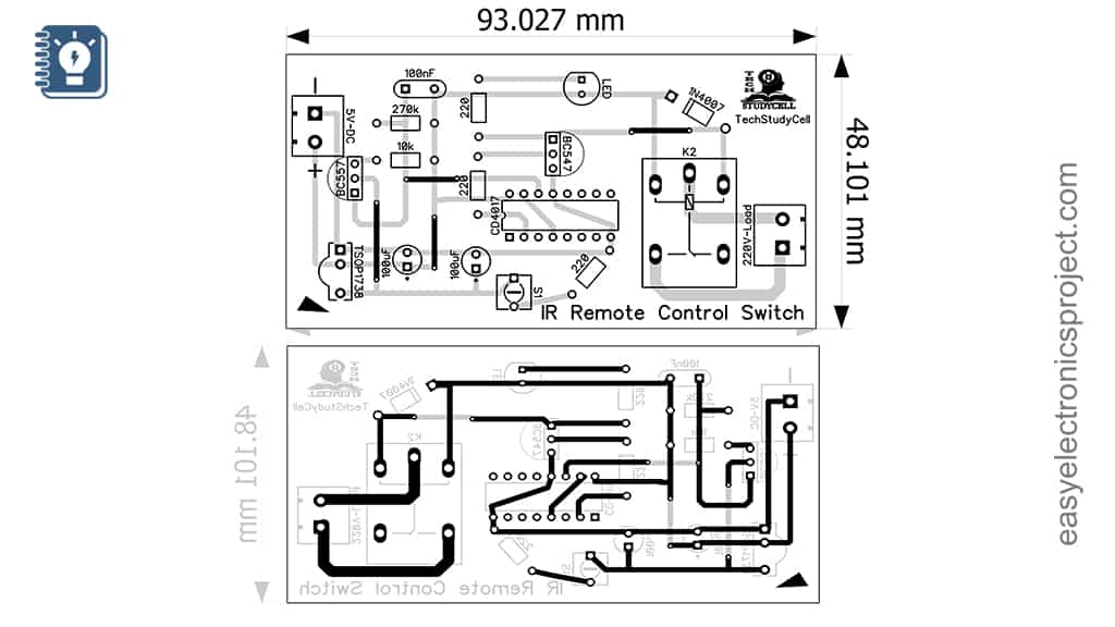
Please download the PCB layout, then print it on the A4 page.
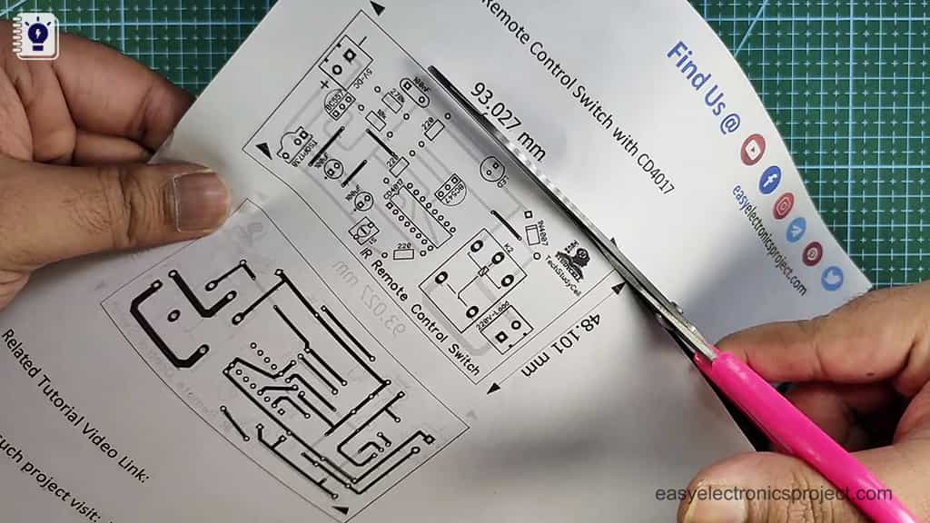
Please check the PCB size while printing, it should be the same as mentioned in Layout.
Required Components for the IC 4017 Project:
- 100uF DC 16V capacitors 2no
- 1000uF 16V DC capacitor
- 0.1 uF Capacitor
- 220-ohm 0.25-watt resistors 3 no
- 10k 0.25-watt resistor
- 270k 0.25-watt resistor
- BC557 PNP Transistor
- BC547 NPN Transistor
- CD4017 IC
- TSOP 1738 IR Receiver
- 1N4007 Diode
- 5-volt SPDT Relay
- Push Button
- 5 volt DC source.
Tutorial Video on IR Remote Light Switch
In the tutorial video, I have explained all the steps to make the homemade PCB for the infrared remote switch circuit. To make the PCB I have used an acrylic sheet.
But you can also download the PCB Gerber file for this 4017 project, and order the custom design PCB from PCBWay.com
About PCBWay and their services

No Minimum Requirement
You may order as small as 5pcs of PCB from PCBWay. You can place an order as per your requirement.
Fair Pricing
Their pricing structure is transparent and has no hidden cost in it and the price is one of the most competitive in the world. Many price-sensitive customers like students and hobbyists largely rely on PCBWay for their PCB prototype, low-volume fabrication, and assembly needs.
Free DFM
All your orders will be receiving a free engineering file review service from trained and professional technicians before the payment.
On-time Shipping
Their on-time delivery rate of 99%. They make sure that your PCBs will be on your desk as scheduled and as early as possible. You can choose DHL and other courier services for the balance of speed and budget.
Return and Refund
In case our PCB or assembled boards are not usable due to their fault, you can ask for compensation. They will refund your account directly or credit your PCBWay account. They can also rework the unusable boards or re-fabricate the PCB and re-ship to you at their cost.
24 hours Customer Service
Whenever you have any problems, you can always reach a live customer service person to respond to your emails or messages related to the order.
For the online instant quote page please visit – pcbway.com/orderonline
For more details please visit the following articles.
Why PCBway
PCB Capabilities
High-Quality PCB
Steps to order PCB from PCBWay
To order the PCB first visit PCBWay.com.

Then enter the following details:
- PCB Size (Length & Width) in mm & PCB quantity
- Select masking color for the PCB
- Select country and shipping method
- Click on the “Save to Cart” button
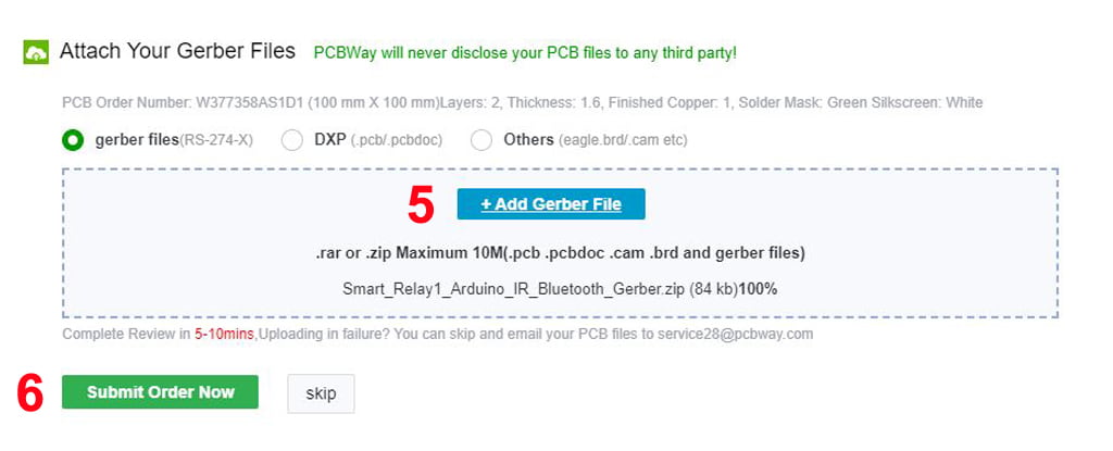
Now click on the “Add Gerber Files” to upload the PCB Gerber file.
Then click on the “Submit Order Now” to place the order.
After that, they will review the Gerber file and accordingly confirm the order.
I have used their services for my different electronics projects, I always received the PCB on time and the quality is very good in this price range.
How to make homemade PCB for the IC 4017 Project
Steps for making the IR sensor control light switch on PCB:
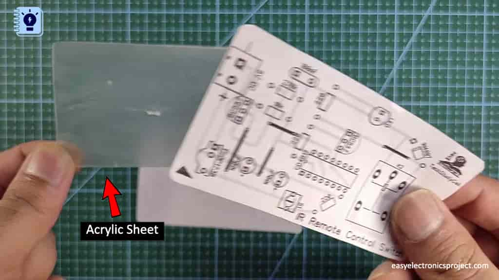
Step 1: Print the PCB Layout and stick it on Acrylic sheet
While printing please check the PCB dimension mentioned in the PCB layout. After downloading the PCB layout, you can print the word file (.docx) on the A4 page (Please refer to the tutorial video).
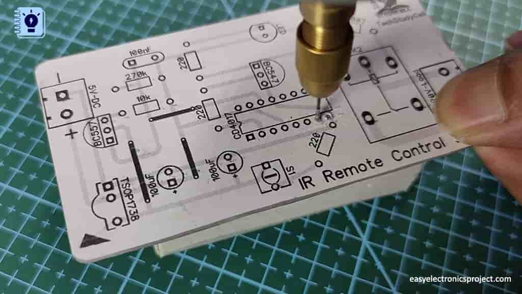
Step 2: Drill the holes for the components on the PCB
Now, drill the holes on the PCB for components as per the PCB layout. You can also use a hand drill or DC motor for drilling.
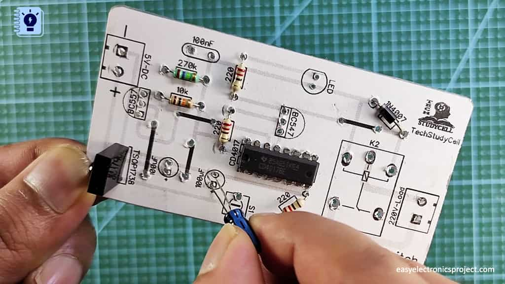
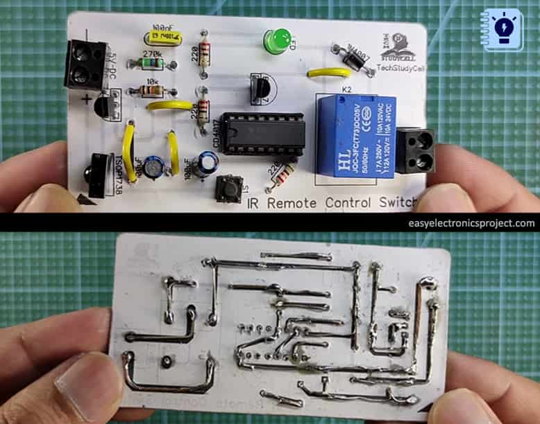
Step 3: Place & Connect all the components as shown on the PCB layout
After that place all the components on the PCB as marked on the PCB. Here I have used extra leads of the components to connect those components for soldering.
Now, our IR Remote control Light Switch PCB is ready.
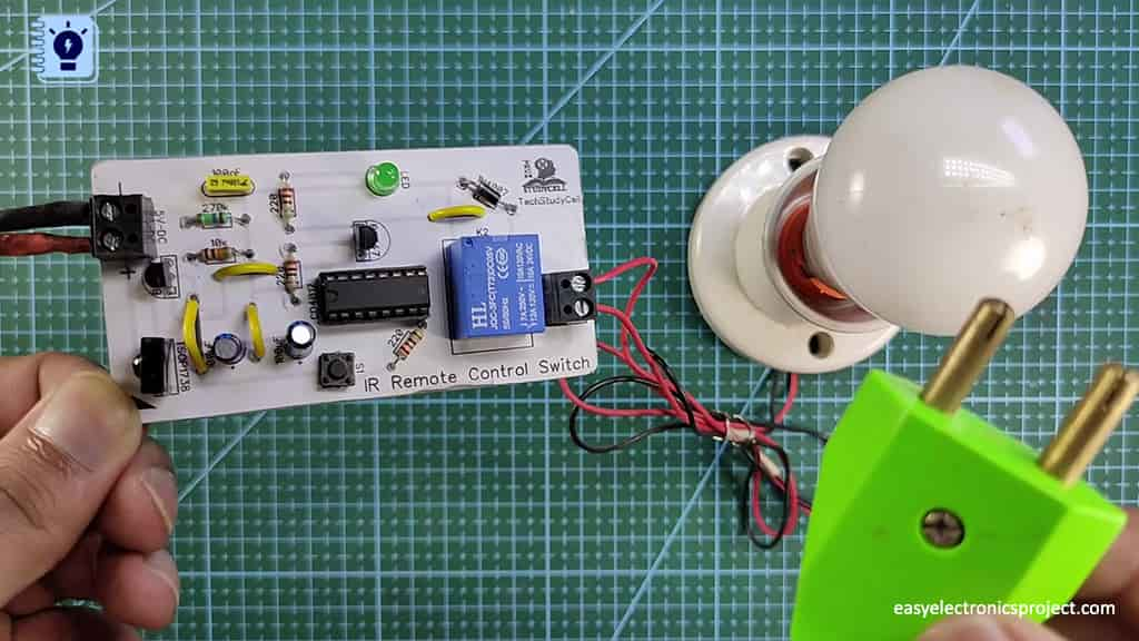
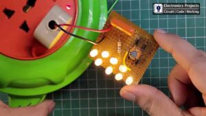
Testing the IR Sensor Switch circuit
Now connect the 5V DC supply and AC bulb as per the circuit.
Please take proper safety precautions while working with 110V \220V AC voltage.
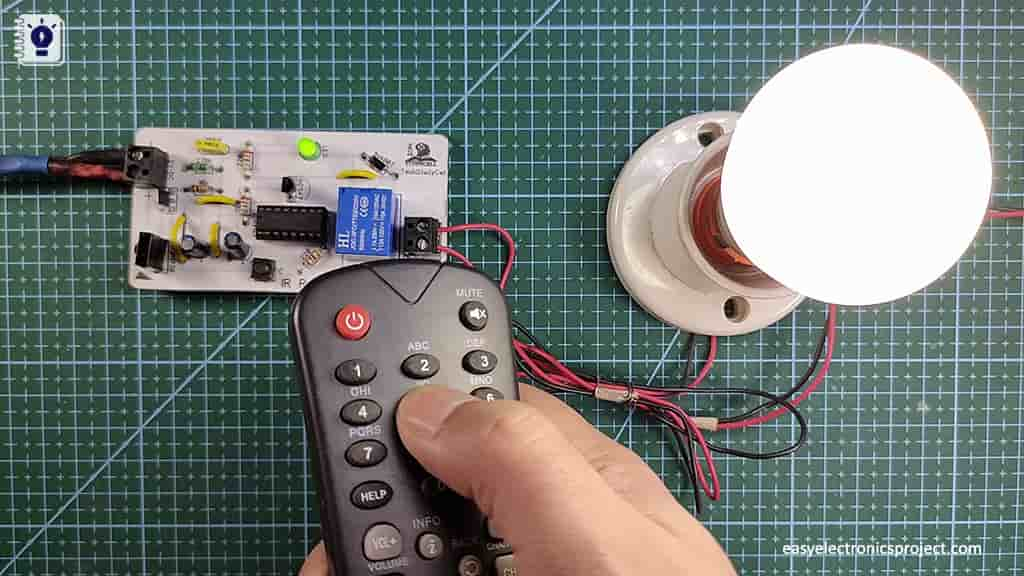
Now, press any button on the IR remote the lamp will turn on. to turn off the lamp press the button again.
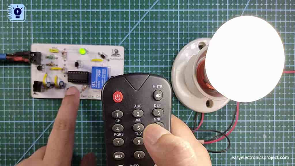
You can also use the push-button to control the lamp manually.
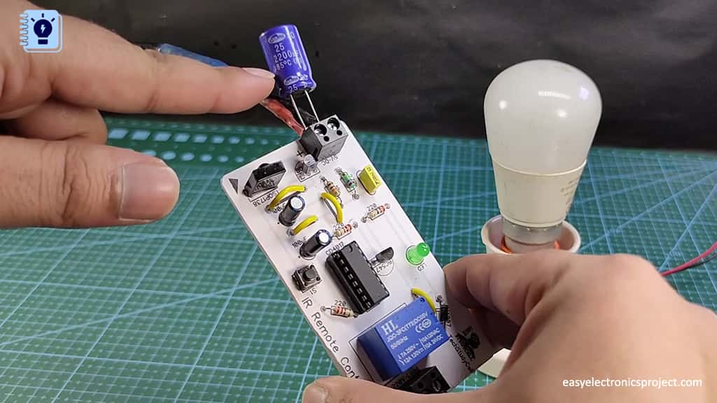
** Please use a 1000uF capacitor across the input.
Please share your feedback on this mini-project and also let me know if you have any queries.
You can also subscribe to our newsletter to receive more such useful electronics projects through email.
I hope you have liked this electronics project, Thank you for your time.