In this IoT project, I have explained how to make a simple ESP8266 MQTT home automation system to control appliances from anywhere through the internet. We will also discuss how to set up the MQTT broker and MQTT client for this home automation project.
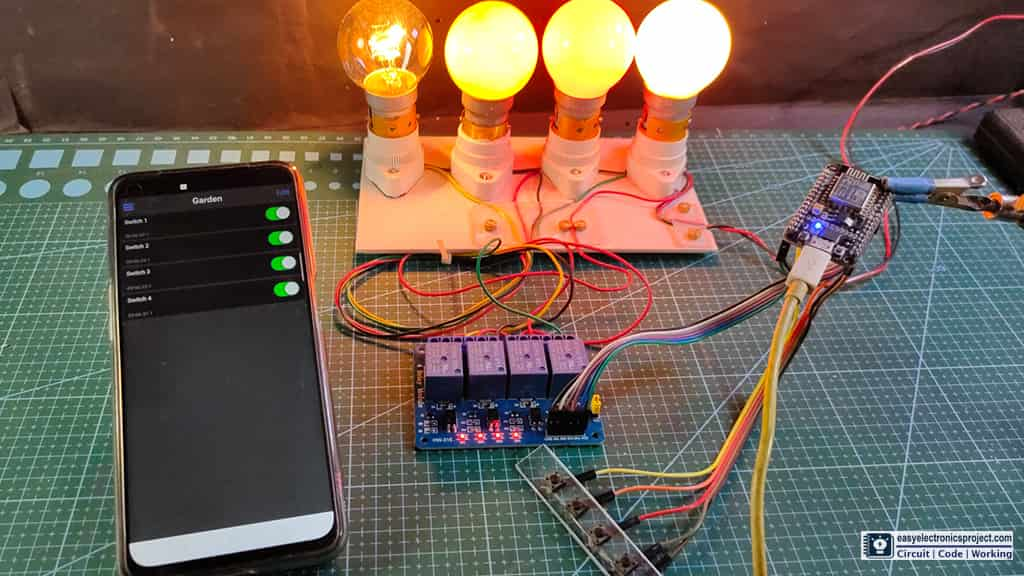
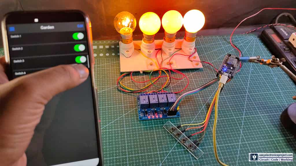
With this MQTT IoT project, you can control 4 appliances from your mobile and also from the manual switches. If the NodeMCU ESP8266 is connected with the WiFi, then you can also monitor the real-time feedback.
Required Components for the ESP8266 MQTT project
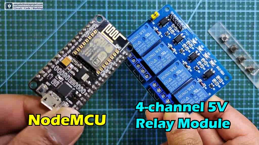
- NodeMCU ESP8266
- 4-channel Relay Module (5V)
- Pushbuttons
Apart from this, you need an MQTT broker. For this project, I have used Reyax RYC1001 as an MQTT broker. But you can use any other MQTT broker.
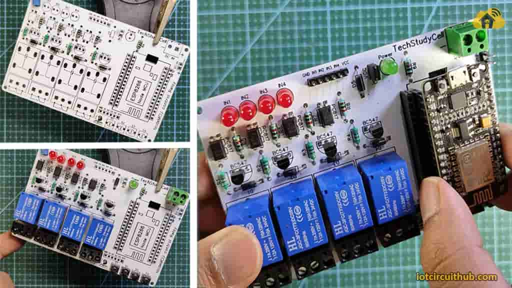
Circuit of the MQTT ESP8266 NodeMCU control relay
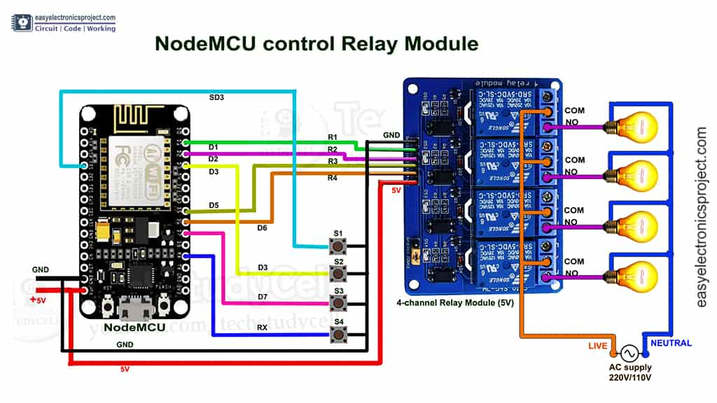
To control the 4-channel relay module, I have used D1, D2, D5, and D6 GPIO pins.
The GPIO SD3, D3, D7 & RX are connected with pushbuttons to control the relay module manually.
Instead of using pull-up resistors with each switch, I have used the INPUT_PULLUP function in Arduino IDE.
As per the source code, when the control pins of the relay module receive the LOW signal the respective relay will turn on and the relay will turn off for the HIGH signal in the control pin.
I have used a 5V 5Amp power supply to supply the NodeMCU and relay module.
Tutorial video on ESP8266 MQTT IoT Project
In the tutorial video, I have covered the following topics
- What is MQTT, How the MQTT protocol works?
- How to set up MQTT broker and MQTT client, and publish/subscribe any topic.
- How to use PubSubClient library to make any MQTT projects.
- Set up IoT OnOff app to control appliances from smartphone.
How MQTT protocol works?
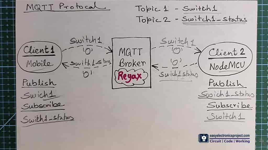
In this project, NodeMCU & “IoT OnOff” (mobile) will act as MQTT clients and Reyax RYC1001 is an MQTT broker.
In MQTT, each client can publish/subscribe to any topic. The topic is like a channel, which can be used to send/receive data through the MQTT broker.
Here, I have created the topic “switch1” to control the relay-1, and the topic “switch1_status” to get the feedback.
The NodeMCU (MQTT client) will subscribe to the “switch1” topic and publish data on the “switch1_status” topic.
In this project, when NodeMCU received “0” on the “switch1” topic, it will turn on the relay-1, and for “1“, it will turn off the relay-1.
After turning ON/OFF the relay-1, the NodeMCU will publish the status (“0″/”1”) on “switch1_status” topic.
The “IoT OnOff” app will receive the feedback sent by NodeMCU on the “switch1_status” topic.
Thus we can control the relay-1, and monitor the real-time status in the “IoT OnOff” app (mobile).
In the video, I have explained in detail how the MQTT protocol works, and how the MQTT client can publish or subscribe to any topic to send or receive data from the MQTT broker.
MQTT Broker Reyax RYC1001

I have used Reyax RYC1001 as an MQTT broker. You can easily purchase it from Amazon.com.
For more details on RYC1001 please visit reyax.com/products/ryc1001/
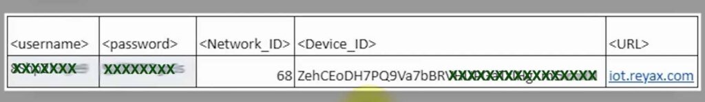
After purchasing the RYC1001, you will get the username, password, Network_ID, Device_ID, URL from Reyax.
You can also use any other MQTT broker, you just have to update the details in the code.
In the tutorial video, I have explained all the details.
PCB for this MQTT ESP8266 IoT project
You can make this project without using any PCB, but if you want to make the circuit compact and give the project a professional look, then download the Gerber file and order the PCB from PCBWay.com.
About PCBWay and their services

PCBWay produces FR-4 and Aluminum boards and advanced PCBs like Rogers, HDI, Flexible and Rigid-Flex boards, at very reasonable prices.
For the online instant quote page please visit – pcbway.com/orderonline
Inspect your Gerber file before placing the order – OnlineGerberViewer
You may order as small as 5pcs of PCB from PCBWay. You can place an order as per your requirement.
You can explore different useful PCB projects from the PCBWay Open-source community – pcbway.com/project
For more details please visit the following articles.
Why PCBway
PCB Capabilities
High-Quality PCB
Steps to order PCB from PCBWay
To order the PCB first visit PCBWay.com.

Then enter the following details:
- PCB Size (Length & Width) in mm & PCB quantity
- Select masking color for the PCB
- Select country and shipping method
- Click on the “Save to Cart” button
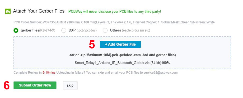
Now click on the “Add Gerber Files” to upload the PCB Gerber file.
Then click on the “Submit Order Now” to place the order.
After that, they will review the Gerber file and accordingly confirm the order.
You will receive the PCB as per the shipping method you have chosen.
Program ESP8266 using Arduino IDE
Steps to program the ESP8266 NodeMCU using Arduino IDE.
- Update the File – Preferences – Aditional boards Manager URLs: https://dl.espressif.com/dl/package_esp32_index.json, http://arduino.esp8266.com/stable/package_esp8266com_index.json
- Then install the ESP8266 board from the Board manager or Click Here to download the ESP8266 board.
- Install all the required libraries in Arduino IDE:
- PubSubClient Library by knolleary and all the dependencies.
Code for the MQTT ESP8266 project
#include <ESP8266WiFi.h>
#include <PubSubClient.h>

// Relays
#define RelayPin1 D1  //D1
#define RelayPin2 D2  //D2
#define RelayPin3 D5  //D5
#define RelayPin4 D6  //D6

// Switches
#define SwitchPin1 10  //SD3
#define SwitchPin2 D3   //D3
#define SwitchPin3 D7  //D7
#define SwitchPin4 3   //RX

//WiFi Status LED
#define wifiLed    D0   //D0

int toggleState_1 = 1; //Define integer to remember the toggle state for relay 1
int toggleState_2 = 1; //Define integer to remember the toggle state for relay 2
int toggleState_3 = 1; //Define integer to remember the toggle state for relay 3
int toggleState_4 = 1; //Define integer to remember the toggle state for relay 4

// Update these with values suitable for your network.

const char* ssid = "WiFi Name"; //WiFI Name
const char* password = "WiFi Password"; //WiFi Password
const char* mqttServer = "iot.reyax.com";
const char* mqttUserName = "Reyax_UserID"; // MQTT username
const char* mqttPwd = "Reyax_Password"; // MQTT password
const char* clientID = "EspClient00002"; // client id


#define sub1 "switch1"
#define sub2 "switch2"
#define sub3 "switch3"
#define sub4 "switch4"

#define pub1 "switch1_status"
#define pub2 "switch2_status"
#define pub3 "switch3_status"
#define pub4 "switch4_status"


WiFiClient espClient;
PubSubClient client(espClient);

unsigned long lastMsg = 0;
#define MSG_BUFFER_SIZE  (80)
char msg[MSG_BUFFER_SIZE];
int value = 0;

void setup_wifi() {
 delay(10);
 WiFi.begin(ssid, password);
 while (WiFi.status() != WL_CONNECTED) {
 delay(500);
 Serial.print(".");
 }
 Serial.println("");
 Serial.println("WiFi connected");
 Serial.println("IP address: ");
 Serial.println(WiFi.localIP());
}

void reconnect() {
 while (!client.connected()) {
 if (client.connect(clientID, mqttUserName, mqttPwd)) {
 Serial.println("MQTT connected");
      // ... and resubscribe
      client.subscribe(sub1);
      client.subscribe(sub2);
      client.subscribe(sub3);
      client.subscribe(sub4);
    }
    else {
      Serial.print("failed, rc=");
      Serial.print(client.state());
      Serial.println(" try again in 5 seconds");
      // Wait 5 seconds before retrying
      delay(5000);
    }
  }
}

void callback(char* topic, byte* payload, unsigned int length) {
  Serial.print("Message arrived [");
  Serial.print(topic);
  Serial.print("] ");

  if (strstr(topic, sub1))
  {
    for (int i = 0; i < length; i++) {
      Serial.print((char)payload[i]);
    }
    Serial.println();
    // Switch on the LED if an 1 was received as first character
    if ((char)payload[0] == '0') {
      digitalWrite(RelayPin1, LOW);   // Turn the LED on (Note that LOW is the voltage level
      toggleState_1 = 0;
      client.publish(pub1, "0");
    } else {
      digitalWrite(RelayPin1, HIGH);  // Turn the LED off by making the voltage HIGH
      toggleState_1 = 1;
      client.publish(pub1, "1");
    }
  }

  else if ( strstr(topic, sub2))
  {
    for (int i = 0; i < length; i++) {
      Serial.print((char)payload[i]);
    }
    Serial.println();
    // Switch on the LED if an 1 was received as first character
    if ((char)payload[0] == '0') {
      digitalWrite(RelayPin2, LOW);   // Turn the LED on (Note that LOW is the voltage level
      toggleState_2 = 0;
      client.publish(pub2, "0");
    } else {
      digitalWrite(RelayPin2, HIGH);  // Turn the LED off by making the voltage HIGH
      toggleState_2 = 1;
      client.publish(pub2, "1");
    }
  }
  else if ( strstr(topic, sub3))
  {
    for (int i = 0; i < length; i++) {
      Serial.print((char)payload[i]);
    }
    Serial.println();
    // Switch on the LED if an 1 was received as first character
    if ((char)payload[0] == '0') {
      digitalWrite(RelayPin3, LOW);   // Turn the LED on (Note that LOW is the voltage level
      toggleState_3 = 0;
      client.publish(pub3, "0");
    } else {
      digitalWrite(RelayPin3, HIGH);  // Turn the LED off by making the voltage HIGH
      toggleState_3 = 1;
      client.publish(pub3, "1");
    }
  }
  else if ( strstr(topic, sub4))
  {
    for (int i = 0; i < length; i++) {
      Serial.print((char)payload[i]);
    }
    Serial.println();
    // Switch on the LED if an 1 was received as first character
    if ((char)payload[0] == '0') {
      digitalWrite(RelayPin4, LOW);   // Turn the LED on (Note that LOW is the voltage level
      toggleState_4 = 0;
      client.publish(pub4, "0");
    } else {
      digitalWrite(RelayPin4, HIGH);  // Turn the LED off by making the voltage HIGH
      toggleState_4 = 1;
      client.publish(pub4, "1");
    }
  }
  else
  {
    Serial.println("unsubscribed topic");
  }
}

void manual_control(){
    //Manual Switch Control
    if (digitalRead(SwitchPin1) == LOW){
      delay(200);
      if(toggleState_1 == 1){
        digitalWrite(RelayPin1, LOW); // turn on relay 1
        toggleState_1 = 0;
        client.publish(pub1, "0");
        Serial.println("Device1 ON");
        }
      else{
        digitalWrite(RelayPin1, HIGH); // turn off relay 1
        toggleState_1 = 1;
        client.publish(pub1, "1");
        Serial.println("Device1 OFF");
        }
     }
    else if (digitalRead(SwitchPin2) == LOW){
      delay(200);
      if(toggleState_2 == 1){
        digitalWrite(RelayPin2, LOW); // turn on relay 2
        toggleState_2 = 0;
        client.publish(pub2, "0");
        Serial.println("Device2 ON");
        }
      else{
        digitalWrite(RelayPin2, HIGH); // turn off relay 2
        toggleState_2 = 1;
        client.publish(pub2, "1");
        Serial.println("Device2 OFF");
        }
    }
    else if (digitalRead(SwitchPin3) == LOW){
      delay(200);
      if(toggleState_3 == 1){
        digitalWrite(RelayPin3, LOW); // turn on relay 3
        toggleState_3 = 0;
        client.publish(pub3, "0");
        Serial.println("Device3 ON");
        }
      else{
        digitalWrite(RelayPin3, HIGH); // turn off relay 3
        toggleState_3 = 1;
        client.publish(pub3, "1");
        Serial.println("Device3 OFF");
        }
    }
    else if (digitalRead(SwitchPin4) == LOW){
      delay(200);
      if(toggleState_4 == 1){
        digitalWrite(RelayPin4, LOW); // turn on relay 4
        toggleState_4 = 0;
        client.publish(pub4, "0");
        Serial.println("Device4 ON");
        }
      else{
        digitalWrite(RelayPin4, HIGH); // turn off relay 4
        toggleState_4 = 1;
        client.publish(pub4, "1");
        Serial.println("Device4 OFF");
        }
    }
    delay(100);
}

void setup() {
  Serial.begin(115200);

  pinMode(RelayPin1, OUTPUT);
  pinMode(RelayPin2, OUTPUT);
  pinMode(RelayPin3, OUTPUT);
  pinMode(RelayPin4, OUTPUT);

  pinMode(SwitchPin1, INPUT_PULLUP);
  pinMode(SwitchPin2, INPUT_PULLUP);
  pinMode(SwitchPin3, INPUT_PULLUP);
  pinMode(SwitchPin4, INPUT_PULLUP);

  pinMode(wifiLed, OUTPUT);

  //During Starting all Relays should TURN OFF
  digitalWrite(RelayPin1, HIGH);
  digitalWrite(RelayPin2, HIGH);
  digitalWrite(RelayPin3, HIGH);
  digitalWrite(RelayPin4, HIGH);

  //During Starting WiFi LED should TURN OFF
  digitalWrite(wifiLed, HIGH);

  setup_wifi();
   client.setServer(mqttServer, 1883);
   client.setCallback(callback);
}

void loop() {
  if (!client.connected()) {
    digitalWrite(wifiLed, HIGH);
    reconnect();
  }
  else{
    digitalWrite(wifiLed, LOW);
    manual_control();
  }
  client.loop();
}
After uploading the code to ESP8266 NodeMCU, you have to set up the MQTT client in mobile. For that, I have used the “IoT OnOff” app as an MQTT client. Again, you can use any other app as an MQTT client.
Set Up IoT OnOff app as MQTT client
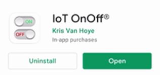
First, install the IoT OnOff app from Google Play Store or App Store.
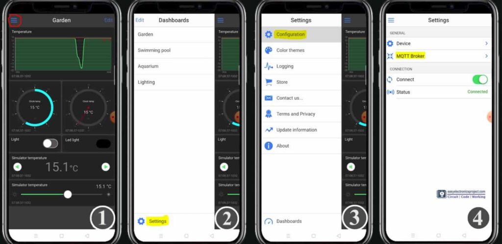
- After login tap on the 3-dash icon on the left.
- Go to Settings.
- Tap on Configuration.
- Tap on MQTT Broker.
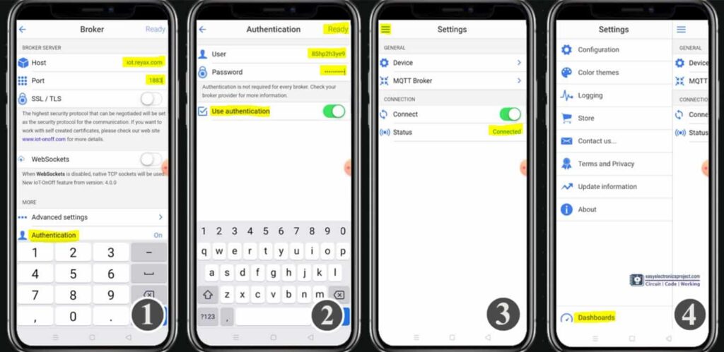
- Enter the Host as iot.reyax.com and Port 1883. Then tap on Authentication.
- Enter the username and password provided by Reyax. Then tap on Ready.
- If all details are correct, the Status should be Connected. Then tap on the 3-dash icon.
- Tap on Dashboards, then go to Garden.
Publish/Subscribe to topic
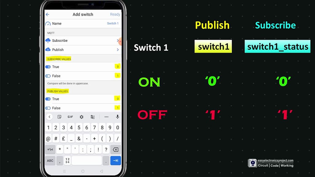
In the “IoT OnOff” app, you have to add a Switch widget and configure publish and subscribe details.
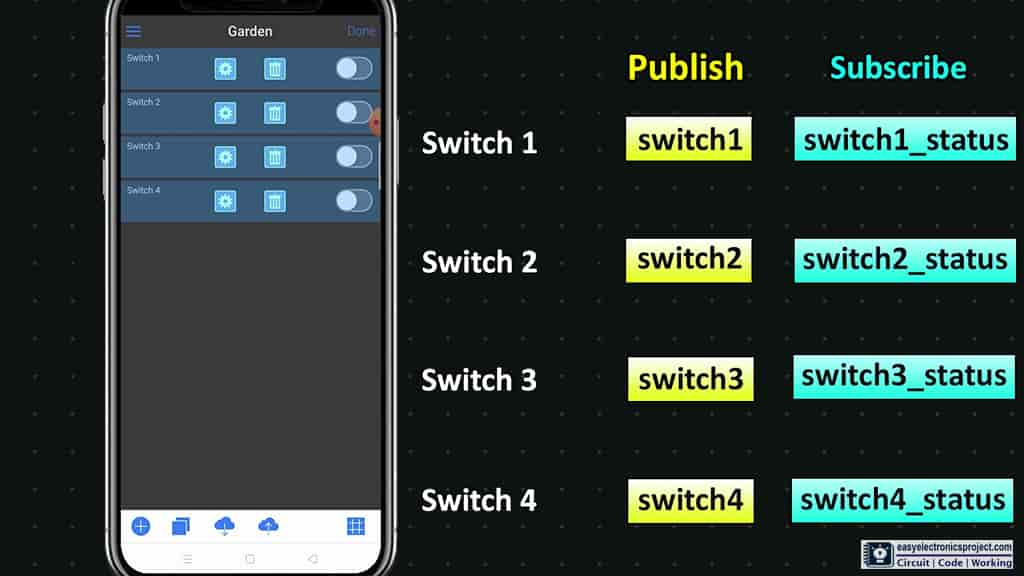
In a similar way, you have to add a total of 4 Switch widgets to control 4 relays.
Please refer to the tutorial video for more details.
ESP8266 control relay with MQTT
After all these steps, if the NodeMCU is connected with Wi-Fi, you can control the appliances from your smartphone through MQTT.
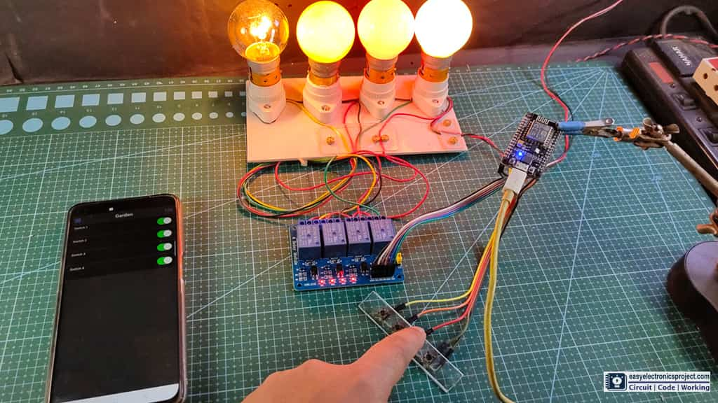
You can also control the appliances manually from pushbuttons. After controlling the relay the ESP8266 will send the feedback to the MQTT broker.
Please share your feedback on this NodeMCU project, and also let me know if you have any queries.
You can also subscribe to our newsletter to receive more such useful electronics projects through email.
I hope you have liked this project, Thank you for your time.
