Description:
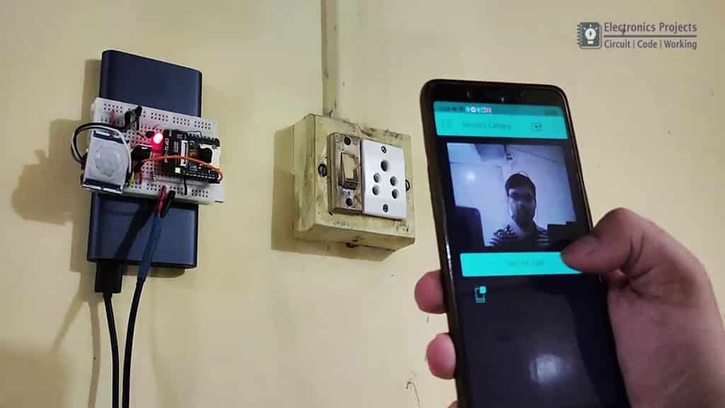
In this ESP32CAM Blynk project, I have made a DIY Home surveillance system with ESP32 CAM, PIR motion sensor, and Blynk app. If any motion detected by PIR sensor, the ESP32-CAM Motion Sensor Security Camera will send a notification to smartphone with the photo.
Circuit Diagram of ESP32CAM project:
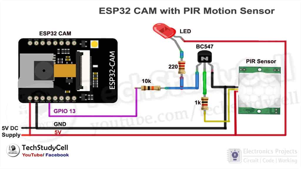
The circuit is very simple. So you can easily make this motion sensor security camera using the ESP32 CAM board, PIR motion sensor.
Component Required for this ESP32CAM Blynk project:
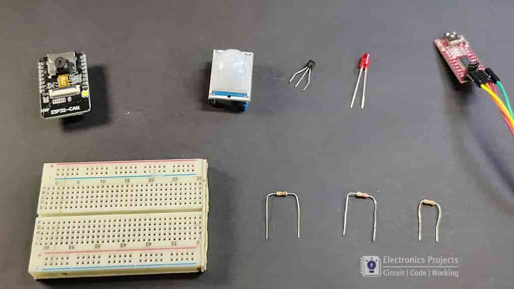
- ESP32-CAM (AI Thinker)
- PIR Motion Sensor Module
- BC547 NPN Transistor
- 220ohm, 1k, 10k Resistor.
- LED
- FTDI 232 USB to Serial Interface board
- 5 volt DC supply
Breadboard Schematic for this ESP32CAM Blynk project
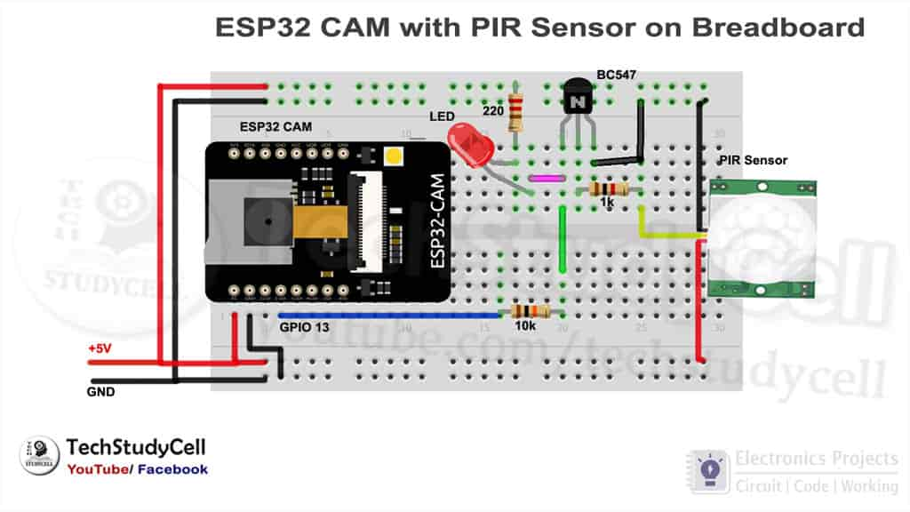
This the breadboard schematic of the motion sensor camera using ESP32-CAM. This will help you to design the ESP32CAM PIR motion sensor camera circuit on the breadboard.
Programming ESP32-CAM board
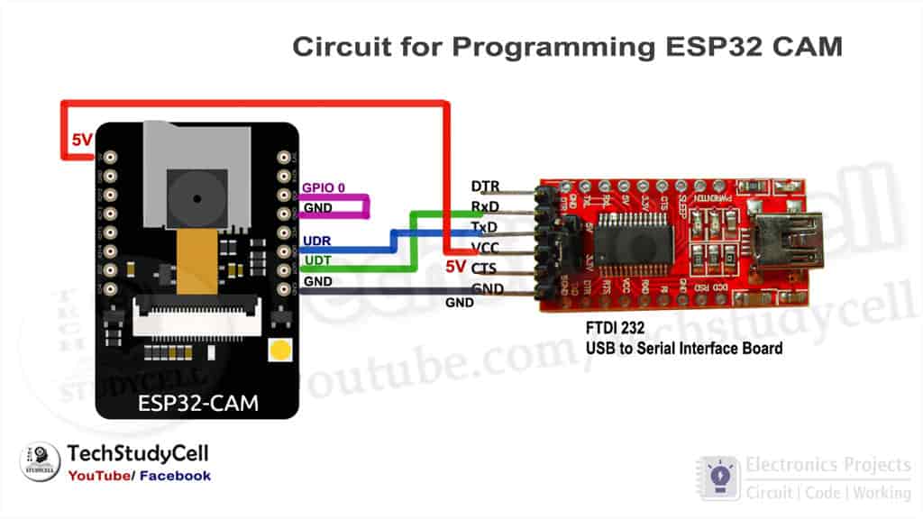
To program the ESP32CAM, I have used FTDI232 USB to Serial interface board. I have connected the FTDI232 with ESP32CAM as per the above circuit.
While uploading the code we have to connect GPIO 0 with the GND pin of ESP32CAM.
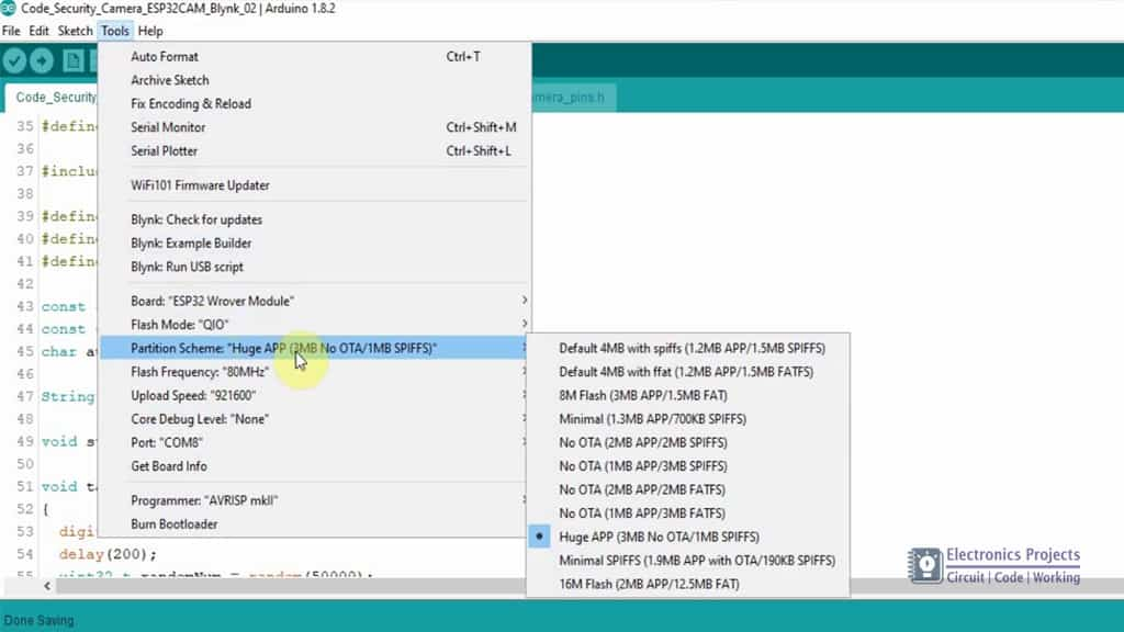
Before uploading the code to ESP32CAM, please check the following setting:
- Update the Preferences –> Aditional boards Manager URLs: https://dl.espressif.com/dl/package_esp32_index.json, http://arduino.esp8266.com/stable/package_esp8266com_index.json
- Board Settings:
- Board: “ESP32 Wrover Module”
- Upload Speed: “921600”
- Flash Frequency: “80MHz”
- Flash Mode: “QIO”
- Partition Scheme: “Hue APP (3MB No OTA/1MB SPIFFS)”
- Core Debug Level: “None”
- COM Port: Depends On Your System
- GPIO 0 must be connected to GND pin while uploading the sketch
- After connecting GPIO 0 to GND pin, press the ESP32 CAM on-board RESET button to put the board in flashing mode
Tutorial video of this IoT project
In this esp32cam tutorial video, I have shown how to make this DIY Home surveillance system using ESP32-CAM step by step. For better understanding please watch the complete video.
Blynk App setup for this ESP32CAM Blynk Project
In the tutorial video, I have explained how to use the Blynk app to control the motion sensor security camera in detail.
Steps for the Blynk App setup:
Open the project in the Blynk AppClickon the “+” icon on the top.
- Select the Image Gallery Widget from the Widget Box
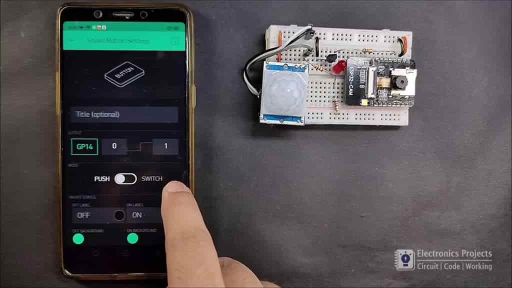
(Setting: Pin- V1) (Function: show the image) - Select the Styled Button from the Widget Box
(Setting: Pin- GP14, Mode- PUSH) (Function: capture photo) - Select the Notification from the Widget Box
(Function: get the notification)
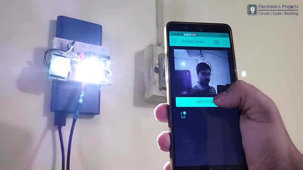
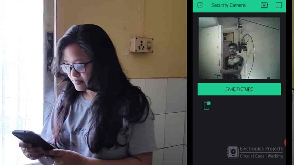
Testing the ESP32CAM security camera
After the Blynk app setup I have tested the circuit.
Supply 5V DC to this security camera circuit and connect your smartphone with the same WiFi network.
Now if the PIR sensor detects any motion, you should get a notification on the mobile phone.
After that click on the ‘Take Picture’ button to get the picture.
The camera can also take pictures in the dark as the inbuilt LED on the ESP32-CAM will provide sufficient light.
I hope you like this Smart home IoT project using ESP32-CAM and Blynk app
You can also subscribe to our newsletter to receive more such useful electronics projects through email.
Please do share your feedback on this ESP32 project. Thank you for your time.
