Description:
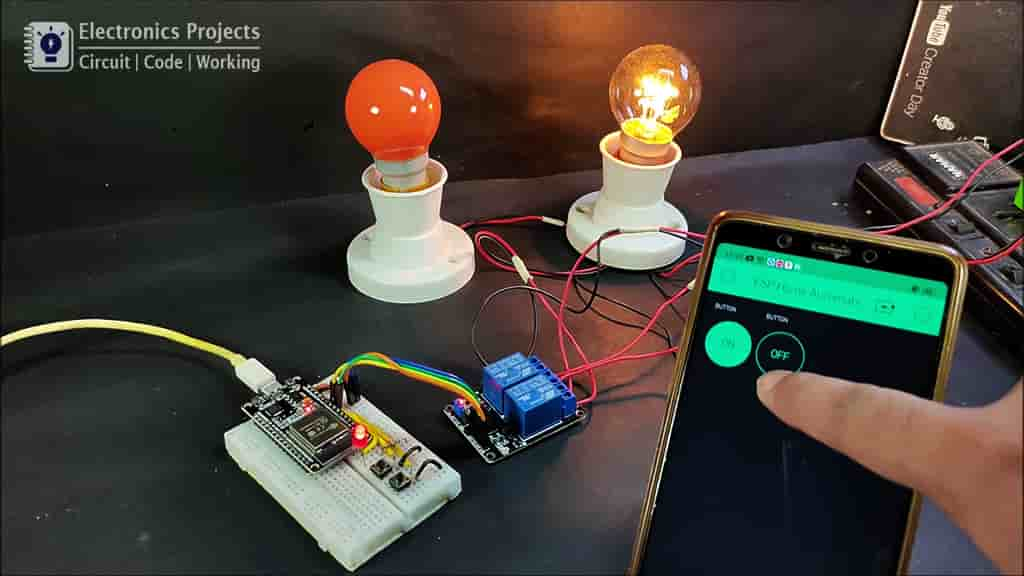
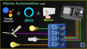
In this IoT project, I have made an ESP32 home automation project using the Blynk App with real-time feedback. If there is no internet, still you can control the relay module manually. You can easily make this smart home device using the ESP32 and relay module.
Circuit Diagram of ESP32 Home Automation
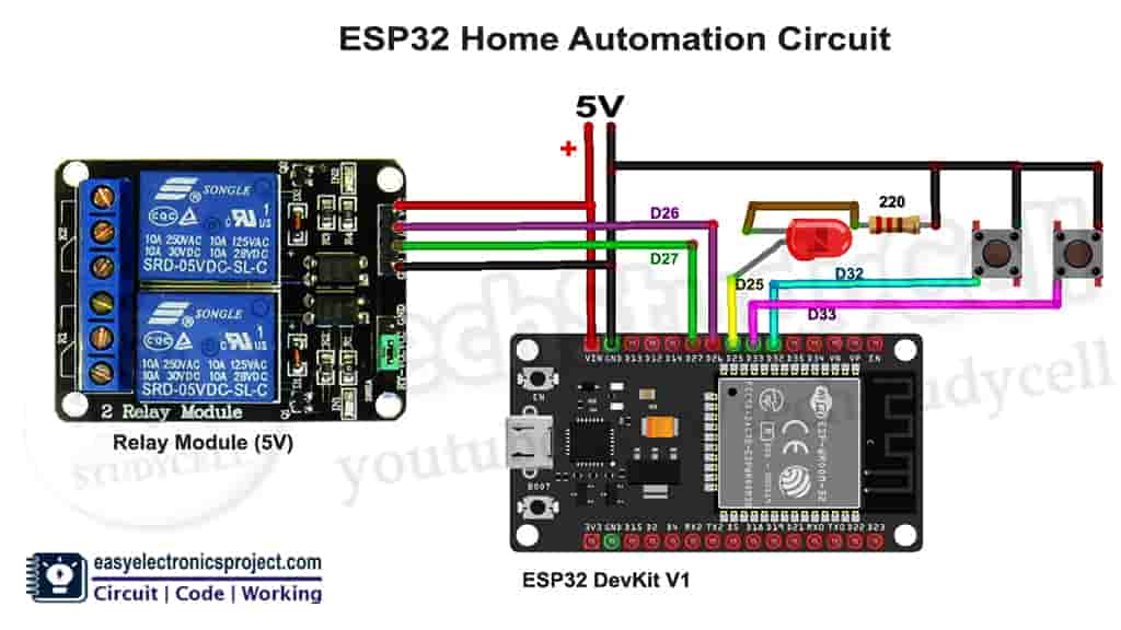
As you can see, the circuit is very simple. You can easily design this smart home project with ESP32 and relay module.
Breadboard schematic for this ESP32 project
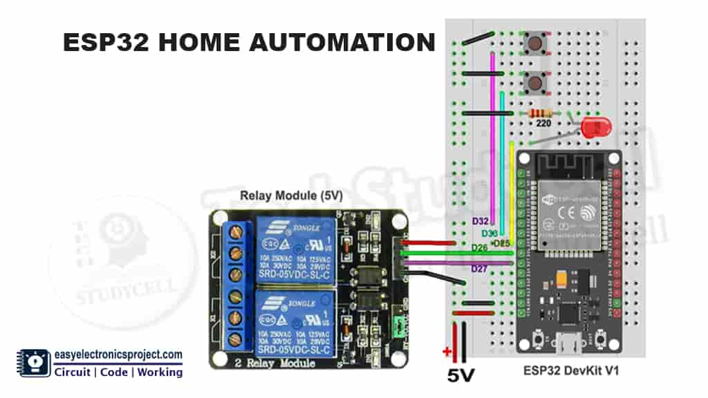
You can refer this breadboard schematic of the ESP32 project to make the circuit on the breadboard.
Required Components:
- ESP32 board (ESP32 DevKit V1)
- Relay Module (5V) Active Low
- 220-ohm resistor
- LED (1.5V)
- push switches (2no)
- Breadboard
Tutorial video for ESP32 Home Automation:
During the video, I have explained the circuit diagram and the code for this IoT project in details. So After watching the complete video, you can easily make this home automation system for your home.
Configure the Blynk App:
First, download the Blynk from Google play store or App store.
Then create a new project in the Blynk app. Enter the project name and choose the device. In this IoT project, I have used ESP32, so I have selected ESP32 Dev Board.
After that Blynk will send an Auth Token to the registered email id. The Auth Token will be required while programming the ESP32.
Now, I have to create switches in the Blynk app to control the relay module.
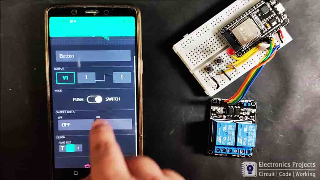
Steps to add the button in Blynk App:
Open the project in the Blynk App, then click on the “+” icon on the top.
select the Button
Click on that button and select the output pin –> V1 & Mode –> Switch
In similar way create switch with V2 pin to control the second relay.
Please refer the tutorial video for adding the buttons in the Blynk App
Programming the ESP32 board
For this smart home project, you have to install the Blynk library before programming the ESP32 board.
Click Here to download latest Blynk library.
Update the Preferences –> Aditional boards Manager URLs: https://dl.espressif.com/dl/package_esp32_index.json, http://arduino.esp8266.com/stable/package_esp8266com_index.json
In the tutorial video, I have explain how the code works in details.
Code for this ESP32 Home Automation Project:
#include <WiFi.h>
#include <WiFiClient.h>
#include <BlynkSimpleEsp32.h>

BlynkTimer timer;

int toggleState_1 = 1;
int pushButton1State = HIGH;

int toggleState_2 = 1;
int pushButton2State = HIGH;

int wifiFlag = 0;

#define AUTH "AUTH TOKEN"                 // You should get Auth Token in the Blynk App.
#define WIFI_SSID "WIFI NAME"             //Enter Wifi Name
#define WIFI_PASS "WIFI PASSWORD"         //Enter wifi Password

#define RELAY_PIN_1      26   //D26
#define RELAY_PIN_2      27   //D27
#define WIFI_LED         25   //D25

#define PUSH_BUTTON_1    32   //D32
#define PUSH_BUTTON_2    33   //D33

#define VPIN_BUTTON_1    V1
#define VPIN_BUTTON_2    V2

void relayOnOff(int relay){

    switch(relay){
      case 1:
             if(toggleState_1 == 0){
              digitalWrite(RELAY_PIN_1, HIGH); // turn on relay 1
              toggleState_1 = 1;
              }
             else{
              digitalWrite(RELAY_PIN_1, LOW); // turn off relay 1
              toggleState_1 = 0;
              }
             delay(200);
      break;
      case 2:
             if(toggleState_2 == 0){
              digitalWrite(RELAY_PIN_2, HIGH); // turn on relay 2
              toggleState_2 = 1;
              }
             else{
              digitalWrite(RELAY_PIN_2, LOW); // turn off relay 2
              toggleState_2 = 0;
              }
             delay(200);
      break;
      default : break;
      }
}

BLYNK_CONNECTED() {
  // Request the latest state from the server
  Blynk.syncVirtual(VPIN_BUTTON_1);
  Blynk.syncVirtual(VPIN_BUTTON_2);
}

// When App button is pushed - switch the state

BLYNK_WRITE(VPIN_BUTTON_1) {
  toggleState_1 = param.asInt();
  digitalWrite(RELAY_PIN_1, toggleState_1);
}

BLYNK_WRITE(VPIN_BUTTON_2) {
  toggleState_2 = param.asInt();
  digitalWrite(RELAY_PIN_2, toggleState_2);
}

void with_internet(){
  if (digitalRead(PUSH_BUTTON_1) == LOW) {
      relayOnOff(1);
      // Update Button Widget
      Blynk.virtualWrite(VPIN_BUTTON_1, toggleState_1);
    }
  if (digitalRead(PUSH_BUTTON_2) == LOW) {
      relayOnOff(2);
      // Update Button Widget
      Blynk.virtualWrite(VPIN_BUTTON_2, toggleState_2);
    }
}
void without_internet(){
  if (digitalRead(PUSH_BUTTON_1) == LOW) {
      relayOnOff(1);
    }
  if (digitalRead(PUSH_BUTTON_2) == LOW) {
      relayOnOff(2);
    }
}

void checkBlynkStatus() { // called every 3 seconds by SimpleTimer

  bool isconnected = Blynk.connected();
  if (isconnected == false) {
    wifiFlag = 1;
    digitalWrite(WIFI_LED, LOW);
  }
  if (isconnected == true) {
    wifiFlag = 0;
    digitalWrite(WIFI_LED, HIGH);
  }
}

void setup()
{
  Serial.begin(9600);

  pinMode(RELAY_PIN_1, OUTPUT);
  pinMode(PUSH_BUTTON_1, INPUT_PULLUP);
  digitalWrite(RELAY_PIN_1, toggleState_1);

  pinMode(RELAY_PIN_2, OUTPUT);
  pinMode(PUSH_BUTTON_2, INPUT_PULLUP);
  digitalWrite(RELAY_PIN_2, toggleState_2);

  pinMode(WIFI_LED, OUTPUT);

  WiFi.begin(WIFI_SSID, WIFI_PASS);
  timer.setInterval(3000L, checkBlynkStatus); // check if Blynk server is connected every 3 seconds
  Blynk.config(AUTH);
}

void loop()
{
  if (WiFi.status() != WL_CONNECTED)
  {
    Serial.println("Not Connected");
  }
  else
  {
    Serial.println(" Connected");
    Blynk.run();
  }

  timer.run(); // Initiates SimpleTimer
  if (wifiFlag == 0)
    with_internet();
  else
    without_internet();
}Enter the following details in the code:
- Auth Token received in Email at “Auth Token”
- WiFi Name at “WiFi Name”
- WiFi Password at “WiFi Password”
Now select the ESP32 DEVKIT V1 board and PORT in Arduino IDE. Now click on the upload button to program the ESP32.
Connect the Home Appliances
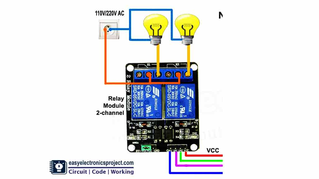
Now, connect the home appliances with the relay module as per the circuit diagram.
Please take proper safety precaution while working with high voltage.
Controlling AC Lamps from Push Buttons and Blynk App
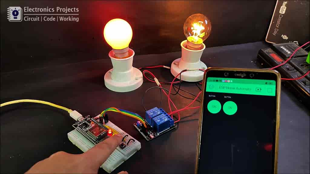
If the WiFi is connected then we can control the home appliances both from push buttons and the Blynk App. And we can also monitor the real time feedback of the switch on the Blynk App.
Controlling the Lamp without WiFi
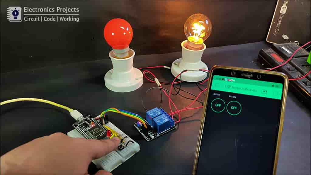
If there is no internet, the ESP32 will move to the “No WiFi” mode, and the Red LED will turn off.
In this mode we can control the Lamps from the push buttons only.
When the internet comes back the ESP32 will move to “with WiFi” mode automatically, and the Red LED will turn on.
I hope you like this Smart home IoT project using the ESP32 and Blynk app.
Click Here for more such ESP32 projects.
You can also subscribe to our newsletter to receive more such useful electronics projects through email.
Please do share your feedback on this ESP32 project. Thank you for your time.