Description:
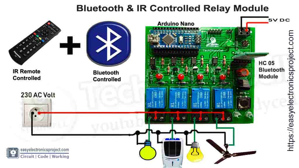
In this Arduino project, I have explained how to control light, fan, and other home appliances from smartphone bluetooth and IR remote using a Arduino control relay module.
Circuit of the Arduino Control Relay
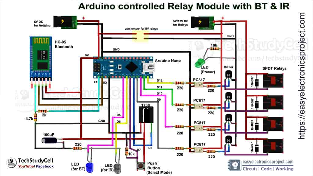
This is the complete circuit for this home automation project.
This Arduino controlled relay circuit has two modes, Bluetooth mode, and Infrared mode. so we can control home appliances with both Mobile Bluetooth and IR remote.
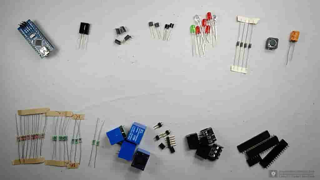
Required Component List:
1. Arduino Nano
2. HC 05 Bluetooth Module
3. TSOP 1738 IR Receiver
4. Transistor BC547 (4 no)
5. PC817 Optocoupler (4 no)
6. 100uF Capacitor (1no)
7. LEDs (1.5 or 3V) (7 no)
8. Diode 1N4007 (4 no)
9. SPDT Relay 5v (4 no)
10. 1 k Resistor (6 no)
11. 220-ohm Resistors (8 no)
12. 2k Resistor (1 no)
13. 4.7k Resistor (1 no)
14. 10k Resistor (1 no)
15. Male & Female connectors (2mm Pitch Female BERG Strip)
Tutorial video of Arduino Control Relay
I have explained all the details in the related videos.
Infrared Controlled Mode
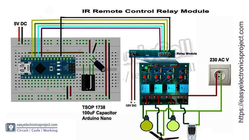
In this part, I have explained the Infrared control circuit. If we press any IR remote button, it sends an Infrared signal (blinking of the IR LED). Then the IR receiver (TSOP1738) receives and decodes the IR signal. Then the Arduino reads the signal and compares it with the predefine Hex codes to control the relay module.
Bluetooth Controlled Mode:
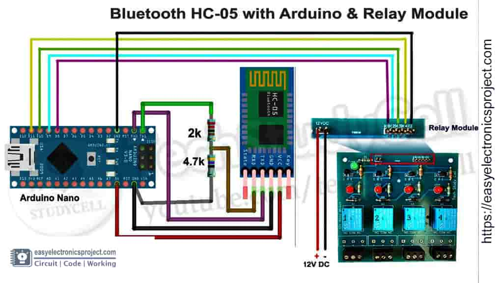
In the Bluetooth control part, I have to connect the smartphone with an HC-05 Bluetooth module. You can use any Bluetooth Application available in the Google Play store. With the Bluetooth App we can send some predefine characters from the smartphone to the HC-05 Bluetooth module. Then Arduino reads and compares the characters received from the HC-05 module to control the Relays.
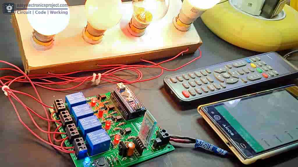
Infrared and Bluetooth Control Relay Module
In this project, I have combined the Infrared control and the Bluetooth control circuit on a single PCB.
To change the mode (Infrared or Bluetooth) I have used a push button. Please refer the complete circuit diagram shared on the top.
After downloading the Arduino code, you have to modify the code as per the IR remote and the Bluetooth app you will use in this home automation project.
PCB for the Arduino Project
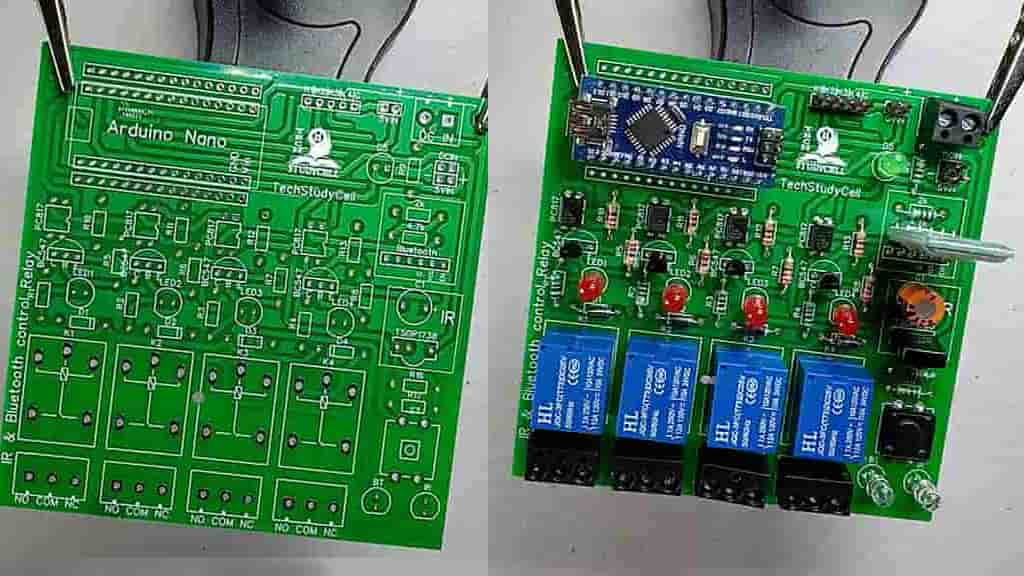
To make the circuit compact and give the project a professional look, I have designed a PCB for this circuit.
You can download the PCB Garber file from the following link:
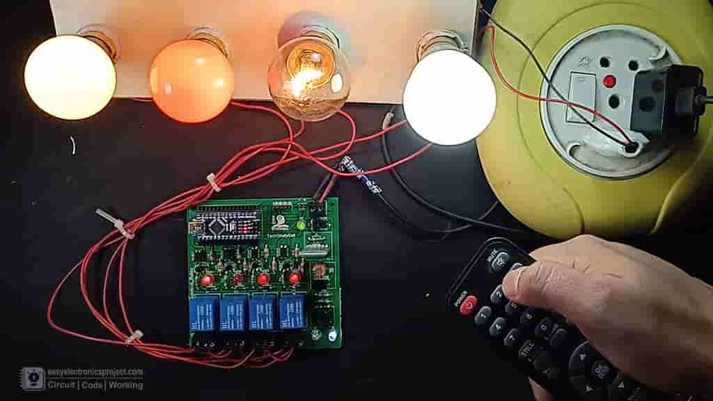
Control relay with IR remote
There are two indicator LEDs on the PCB. The white LED is for Infrared Mode and the blue LED is for Bluetooth Mode.
Now, if I press the push button once then the white LED will turn on which indicates the circuit is in Infrared control mode. At the Infrared mode, I can control the relay module with any IR remote (Example: TV remote).
Control relay with Bluetooth
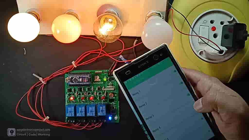
If I press the push button twice then the Bluetooth Mode will activate and the blue LED will turn on. In Bluetooth mode, I can control the relay module from the mobile Bluetooth.
Finally, the Smart Relay Module is Ready
After connecting all the home appliances with the relay module, turn on the 110V/230V AC supply and 5-volt DC supply.
Now the home appliances can be controlled in a smart way.
I hope you have liked this home automation project using Arduino.
You can also subscribe to our newsletter to receive more such useful electronics projects through email.
Please do share your feedback on this Arduino project. Thank you for your time.
