Description:
In this Arduino project, I have shown how to use Lora with Arduino for different IoT projects. Here we will use the Reyax RYLR890 Lora module to design a Lora Arduino circuit that can control a relay module from 10 KM distance.
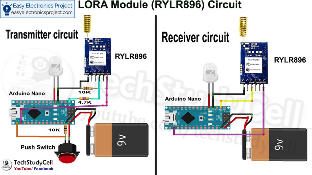
Circuit Diagram:
Component List:
1. Reyax RYLR896 LoRA module 2no
2. Arduino Nano 2no
3. 10k resistor 1no
4. 4.7k resistor 1no
5. LED 5mm 2no
6. Push Switch 1no
7. Breadboard
8. 9volt Battery 2no
9. Relay Module
LoRA Transmitter circuit:
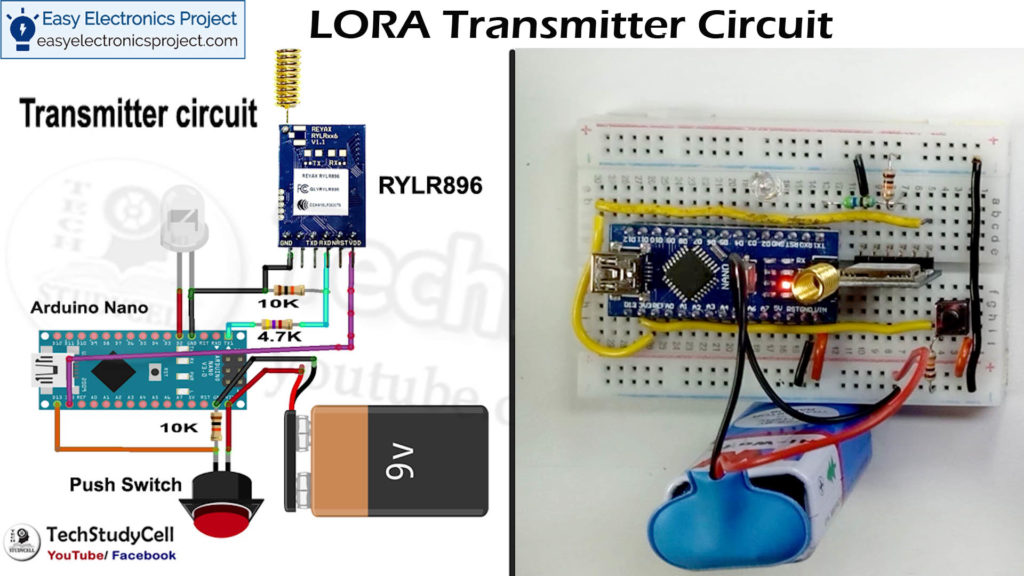
The LORA transmitter circuit will send to signal to LORA receiving circuit.
LoRA Receiver circuit:
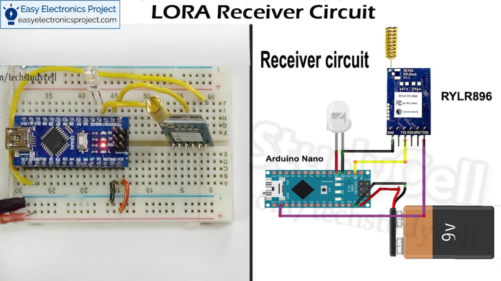
The LORA receiver circuit will receive the signal from the LORA transmitter circuit and accordingly control the Relay module.
Working Principle
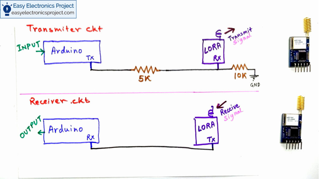
Transmitter circuit:
In the transmitter circuit, the RX pin of the Arduino is connected with the TX pin of the LORA module through a voltage divider.
As the Arduino sends the signal at 5V logic level but the RYLR896 Lora module can receive the signal at 3.3V logic level.
So the voltage divider is required to drop down 5v to 3.3V.
Receiver circuit:
In the receiver Lora circuit, the Arduino RX pin is connected with the TX pin of the LOAR module.
As Arduino can receive the signal at 3.3v logic level from the LORA RYLR896 Module, so no voltage divider is required for the Receiving LoRA circuit.
Configuring the Parameters:
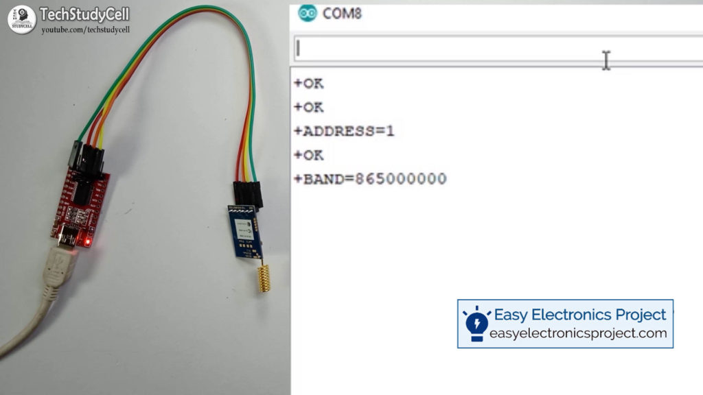
First, we have to configure some parameters of the LoRA module by AT Command.
Some common AT command:
1. Use “AT+ADDRESS” to set the ADDRESS. The ADDRESS is used for the identification of the transmitter or specified receiver.
2. Use “AT+NETWORKID” to set the ID of the Lora network. As this is a group function so the modules can communicate with each other only by setting the same NETWORK ID. If the ADDRESS of the specified receiver belongs to a different group, it can not communicate with each other. The recommended value is 1~15
3. Use ”AT+BAND” to set the frequency of the wireless band. The transmitter and the receiver should use the same frequency to communicate with each other.
4. Use ”AT+PARAMETER” for setting the RF wireless parameters. To communicate with each other, the transmitter and the receiver should set the same parameters.
Please Download the Datasheet to get all the AT commands.
Related Video of Lora Arduino Tutorial
Arduino Code:
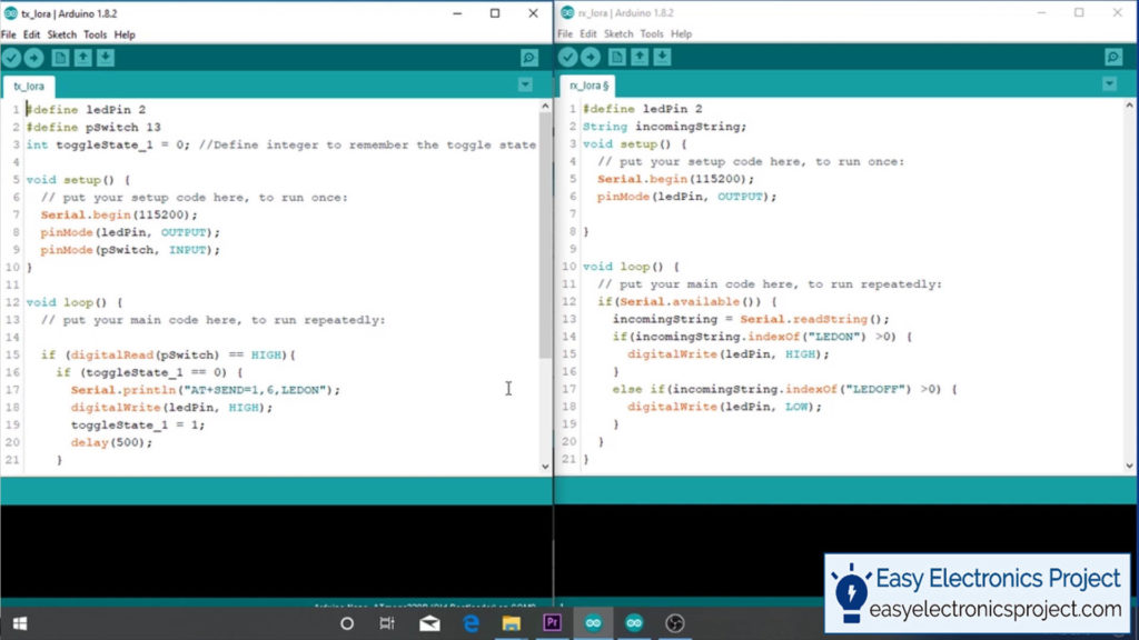
I have explain the complete Arduino sketch in the related video.
Testing the circuit on Breadboard
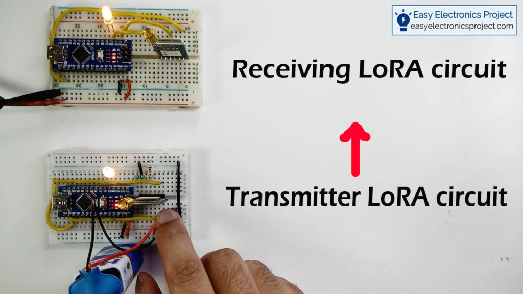
In this project whenever we press the push button on the transmitter circuit, it will send the signal to the Receiving circuit by using AT command.
At the receiving end, it will read the AT command from the signal and accordingly turn on and off the LED connected with the Receiving circuit, Arduino.
Controling the Relay Module with LoRA
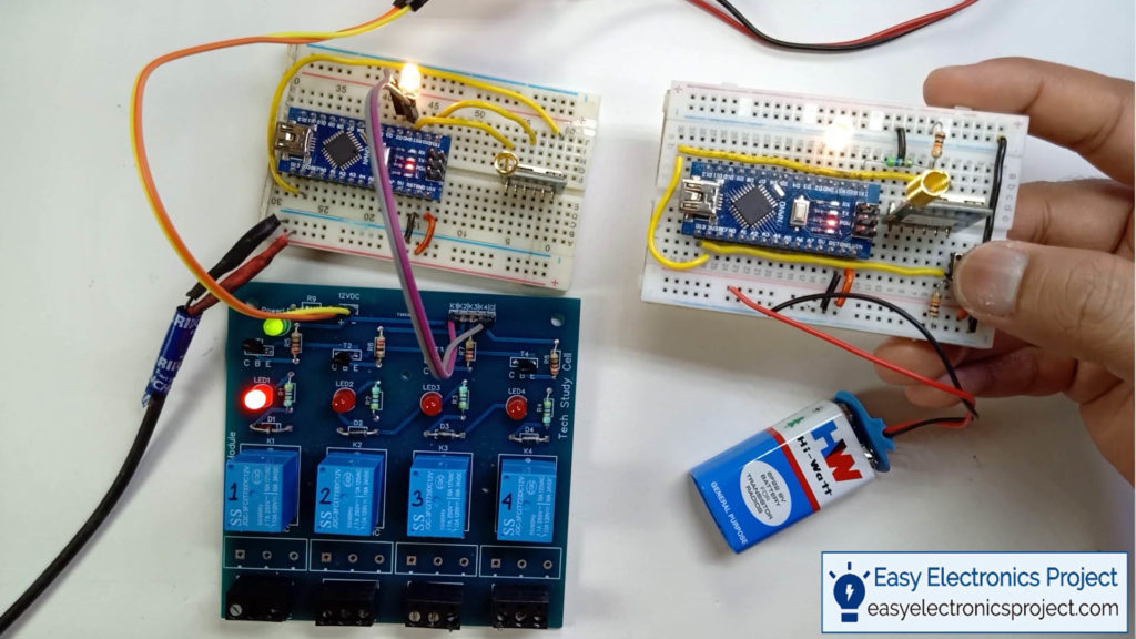
Now we will control a relay module to turn on and off an AC lamp with this LORA circuit
I will really appreciate it if you share your valuable feedback, Also if you have any query please write in the comment section.
Thank you & Happy Learning…
