Description:
In this project, I have made a simple adjustable voltage DC power supply using the LM317. This circuit has an inbuilt bridge rectifier, so I can directly supply 220V or 110V AC supply at the input of the LM317 circuit. The circuit converts 230V / 110V AC to 0v – 12v DC.
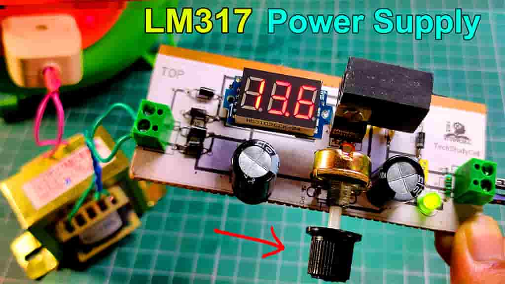
I can also monitor the output voltage on the digital voltmeter, connected with the circuit. I can use this circuit as a variable DC power supply for different electronics projects.
Circuit of LM317 variable DC power supply:
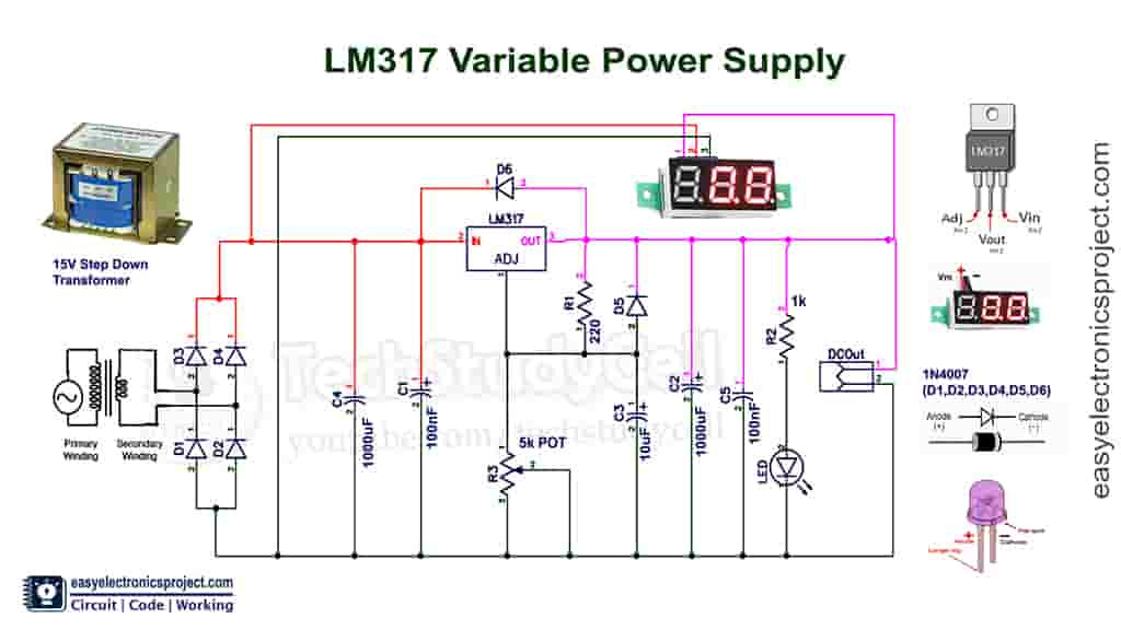
Please refer to this circuit diagram for the LM317 adjustable DC power supply. I have mentioned all the required component’s rating in the circuit diagram.
First, the step-down transformer reduces the voltage from 220V/110V to 15V AC.
Then the inbuilt bridge rectifier converts 15 volt AC to 15 volt DC.
To get the maximum 12volt DC at the output, I need to supply 15volt DC at the input of the LM317 IC.
The output voltage can be adjusted by the potentiometer.
Required Components for LM317 circuit:
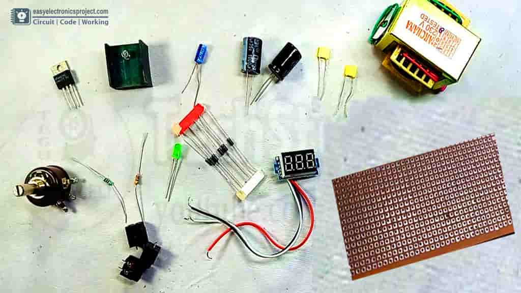
- LM317 IC with heat sink 1no
- 220-ohm resistor 1no
- 1k resistor 1no
- 5k potentiometer 1no
- 10 uF Capacitor 1no
- 1000 uF Capacitors 2no
- 0.1uF Capacitors 2no
- 5-mm LED 1no
- 1N4007 Diodes 6no
- Step Down Transformer 220/110V to 15V
- Digital Voltmeter 0-100V Three Wire (Optional)
- Connectors
- Zero PCB
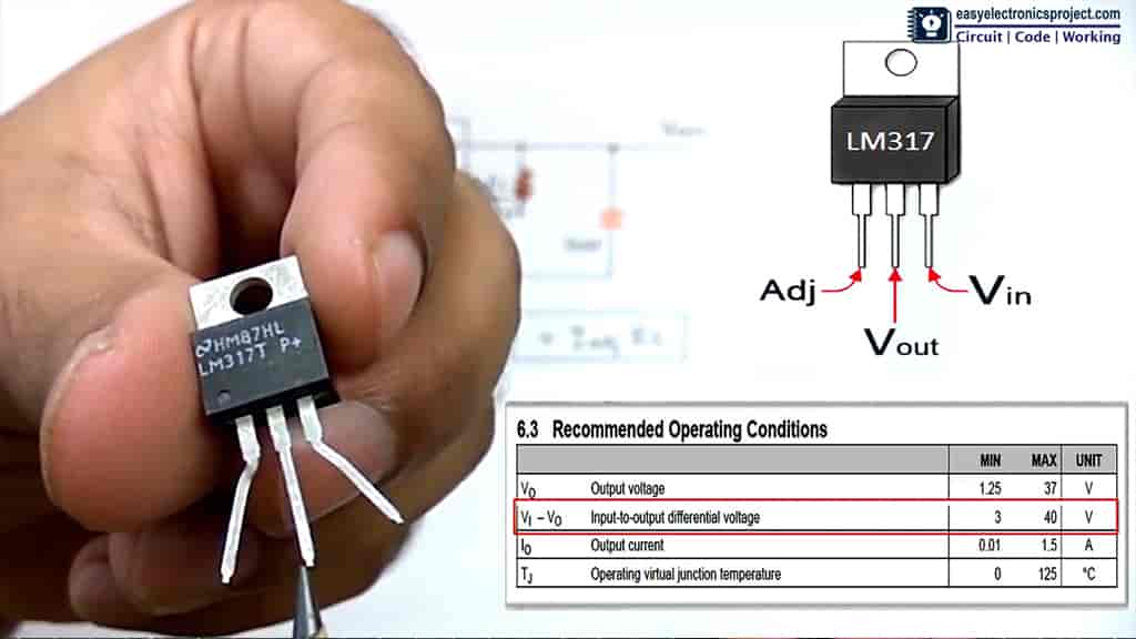
LM317 IC pinout:
Now, before working with the LM317 voltage regulator, we should know the pros & corns of the LM317.
So in this video, I have explained the following topic of LM317 IC which gives you a clear idea about the LM317 regulator
Operating Condition of LM317 IC from the Datasheet [voltage, current, temperature rating, etc]
Explained with voltage equation, how the LM317 circuit works [ use of resistors, capacitors in circuit]
Pinout of LM317t ic [Adjust pin, output pin & input pin]
How to make an adjustable DC power supply with LM317 IC on the breadboard
LM 317 circuit analysis by measuring the input & output voltage using a multimeter.
Using LM317 as a fixed voltage regulator with circuit [LM317 as 7806]
How to calculate the power dissipation in LM317 regulator [ When the heat sink should be used with LM317 IC]
Protections for LM 317 circuit for different applications from LM317 datasheet
I have explained all the features of the LM317 variable voltage regulator with practical experiments, like an LED dimmer, motor speed controller, etc.
Testing LM317 Circuit on Breadboard:
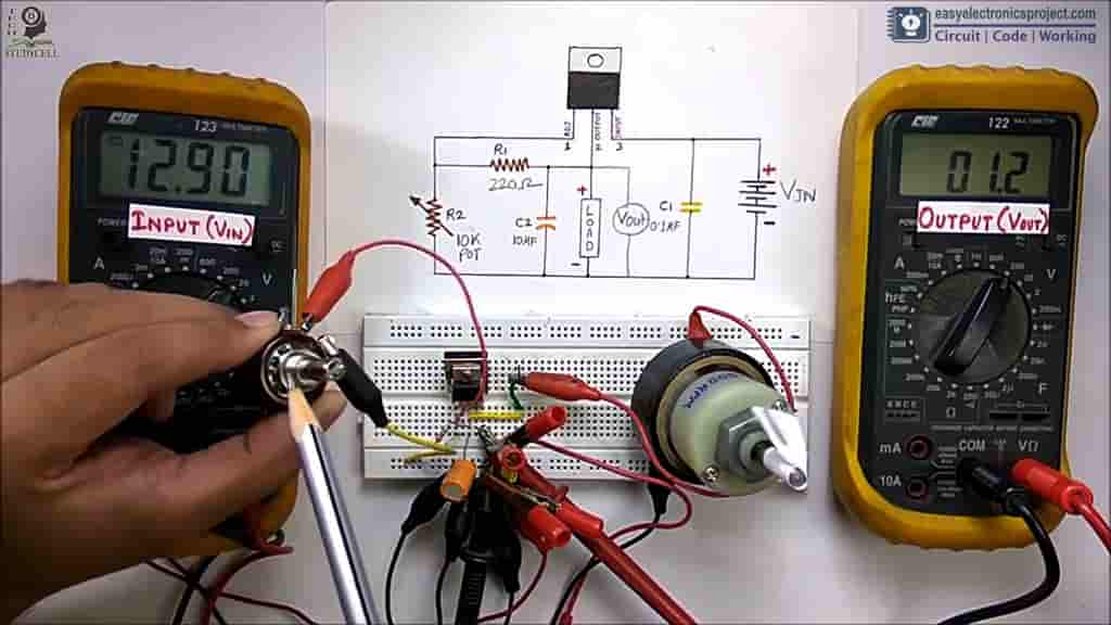
Before designing the PCB, I have made the circuit on the breadboard for testing.
The maximum current limit for this circuit is 1.5Amps and the maximum output voltage is 12 volt DC.
The input voltage will be always greater than the output voltage, as the LM317 is a linear voltage regulator. The efficiency of the circuit decrease with the increases in the difference between input & output voltage.
Tutorial video for the LM317 project:
PCB layout for LM317 Power Supply:
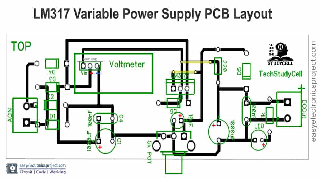
After testing the circuit on Breadboard, I have designed the PCB for this LM317 DC Power Supply which I will use as a power source for different electronics projects.
Download the PCB layout and print it on A4 page. Then stick the layout on Zero PCB and place the components as mentioned.
You can also download the Gerber file for this PCB project, and order it from PCBWay.com.
About PCBWay and their services

PCBWay not only produce FR-4 and Aluminum boards, but also advanced PCB like Rogers, HDI, Flexible and Rigid-Flex boards, with very reasonable price.
For the online instant quote page please visit – pcbway.com/orderonline
Inspect your Gerber file before placing the order – OnlineGerberViewer
You may order as small as 5pcs of PCB from PCBWay. You can place an order as per your requirement.
You can explore different useful PCB projects from PCBWay Open-source community – pcbway.com/project
For more details please visit the following articles.
Why PCBway
PCB Capabilities
High-Quality PCB
Steps to order PCB from PCBWay
To order the PCB first visit PCBWay.com.

Then enter the following details:
- PCB Size (Length & Width) in mm & PCB quantity
- Select masking color for the PCB
- Select country and shipping method
- Click on the “Save to Cart” button
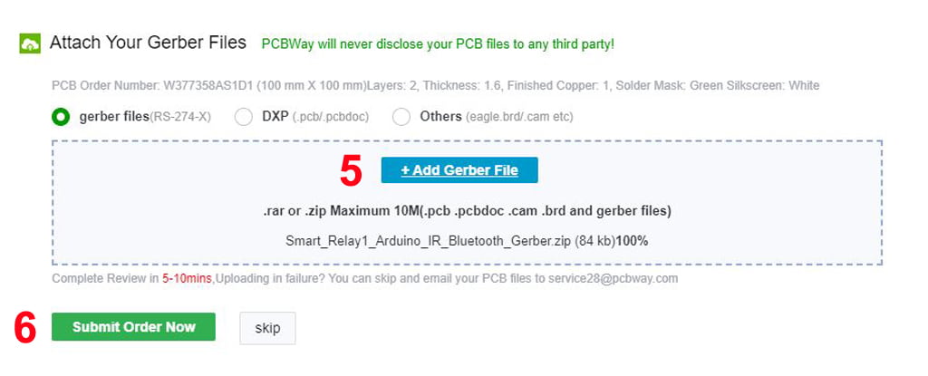
Now click on the “Add Gerber Files” to upload the PCB Gerber file.
Then click on the “Submit Order Now” to place the order.
After that they will review the Gerber file and accordingly confirm the order.
You will receive the PCB as per the shipping method you have chosen.
Placed all the Components on PCB
Now, place all the components on the PCB as shown in the PCB layout.
Place the Diodes, LED, DC Capacitors, and LM317 IC on PCB as per the polarity mentioned in the PCB layout.
Solder the Components on the LM317 PCB
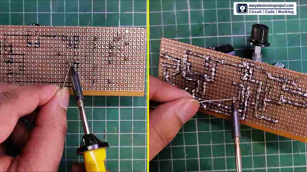
Now, solder all the components as marked on the PCB.
Connect the step-down transformer. Then connect the primary and secondary of the transformer as mentioned in the circuit.
Please take proper precautions while working with the high voltage (110V or 220V AC).
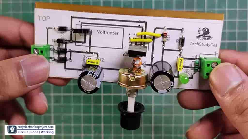
Finally, LM317 Power Supply is ready
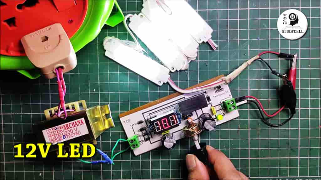
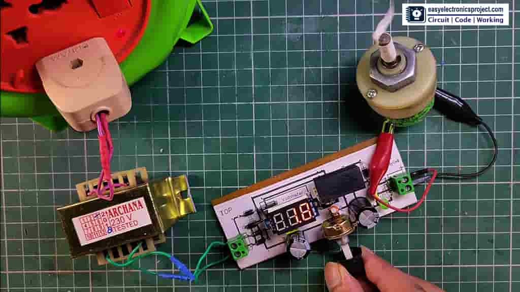
The Adjustable LM317 power supply is ready. Now, I can connect small DC loads like DC motors, LEDs, etc at the output.
The maximum current limit is 1.5Amp and the maximum output voltage is 12Volt DC for this circuit.
Please share your feedback on this mini-project and also let me know if you have any queries.
You can also subscribe to our newsletter to receive more such useful electronics projects through email.
I hope you have liked this project, Thank you for your time.